
 Control Techniques
 Estun Automation
 CODESYS
 Crevis
 Nexcom / Nexcobot
 Leroy-Somer
 Servo Systems
 AC Drive + Motor
 DC Drives
 Smart PLC
 Panel PC / IPC
 Remote I/O
Vision-Based Measurement and Dimensional Inspection
By the ONX Control engineering team · Last updated:
In short
Vision-based measurement is an inspection method that measures a part's length, diameter, height, hole positions or profile cross-section without contact from a calibrated camera image, and compares the result with tolerance limits. The measurement itself is defined by the edges; AI ensures that the part and the features to be measured are reliably located in the image. ONX Control builds this system with an edge AI computer, a GigE camera and suitable lenses and lighting; every part's measurement is logged and out-of-tolerance parts are rejected.
How it works
The chain that determines measurement accuracy is lighting, optics, resolution and calibration. Backlighting gives a sharp silhouette of the part and is the most reliable method for external dimensions; front lighting is used for surface features. The camera and lens are selected so that the whole part, or the region to be measured, is seen at the required mm/pixel resolution; where perspective error is critical, a telecentric lens is preferred.
Calibration converts pixels in the image into millimetres in the real world: a calibration plate of known dimensions is imaged in different positions, and lens distortion and scale are calculated. Measurement is performed by locating edges with sub-pixel precision, and is verified at set intervals with a reference part to account for temperature or mechanical changes.
The role of AI is not to perform the measurement, but to reliably find where to measure: it locates where the part lies in the image and in which orientation, as well as the hole, corner or cross-section region to be measured, even under variable lighting and surface conditions. The measurement result is compared with the tolerance limits; the result goes to the PLC and is logged for every part, and by monitoring the trend a warning can be given before the process drifts out of tolerance.
Dimensions perpendicular to the camera, such as height, cannot be read from a single flat image; laser line triangulation is used instead. A laser line is projected onto the product and the camera views it at an angle; the shift of the line in the image is converted into height in millimetres through calibration. On concrete paving block lines, the line sweeps across each row of blocks as the pallet leaves the press and the height of every block is measured. The aim is to produce blocks consistently close to the minimum height the standard allows and to see a drift the moment the press setting changes; measurements are logged against the pallet number and shown to the operator in real time.
-
1
Calibration
The pixel → mm conversion and lens distortion are calculated with a calibration plate.
-
2
Part and feature location
The model finds the part and the edge, hole or cross-section region to be measured.
-
3
Measurement
Edges are located with sub-pixel precision; length, diameter, distance and angle are calculated.
-
4
Tolerance and logging
The measurement is compared with the tolerance limits; OK/NOK goes to the PLC and every part is logged.
Critical parameters
| Parameter | Why it matters | Value |
|---|---|---|
| Dimension to be measured and tolerance | Determine the required measurement uncertainty and therefore the field of view and resolution. | Defined per project |
| Field of view | The whole part or only one region; large parts need several cameras or a moving scan. | Defined per project |
| Part motion | Whether the part is stationary or moving determines the exposure time, the need for strobe lighting and the camera type. | Defined per project |
| Surface and edge quality | Bright, burred or rounded edges determine the choice of lighting and measurement method. | Defined per project |
| Ambient temperature and vibration | Determine how often calibration is verified and how the camera is mounted. | Defined per project |
The achievable measurement uncertainty depends on the part, the optics and the environment, and is determined in a repeatability test with your reference parts. We do not make general accuracy promises on this page.
ONX architecture
The camera image reaches the edge AI computer over GigE. The part and feature location model runs on the GPU, and edge detection and measurement are performed with OpenCV-based algorithms. Results and measured values go to the PLC via Modbus TCP or OPC UA, and the OK/NOK signal can go directly to a digital output if required.
Thanks to its high resolution, the Crevis MG-A121L-9 in stock (4024 × 3036, 1.85 µm pixels) is suited to viewing a wide area at a fine scale; because it has a rolling shutter, measurement is carried out while the part is stationary or with a strobe in Global Reset mode. The V1628-MPY 12 MP lens in stock matches this resolution; for measurements where perspective is critical, telecentric optics are selected separately.
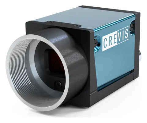
GigE industrial camera and optics
Crevis MG series GigE Vision cameras and 12 MP lenses. Resolution, sensor type (rolling or global shutter), lens and lighting are selected according to the smallest defect and the line speed. The MG-A121L-9 (Sony STARVIS IMX226, rolling shutter + Global Reset) and MG-A121K-9 (Sony Pregius IMX304, global shutter) in stock are powered over PoE on a single cable and triggered from an encoder or photocell through their external trigger input.
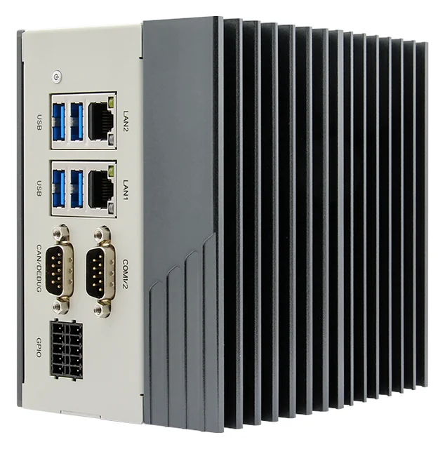
Edge AI computer
Nexcom COEUS-3721T: fanless box PC, NVIDIA Jetson Orin Nano 4 GB (512-core Ampere GPU; manufacturer rating 34 TOPS, INT8, Super mode), 2 × GbE, 4 × USB 3.0, HDMI, 4 DI / 4 DO, RS232/422/485, CAN, 9–30 V DC, DIN rail. Models run on the GPU with TensorRT or ONNX Runtime under Ubuntu 22.04 and JetPack 6.2; images never leave the plant.
PLC and motion control
The decision goes to your existing PLC via a digital output, Modbus TCP or OPC UA. In small cells, CODESYS Control for Linux ARM64 SL can run as the PLC on the same Jetson device.
Image processing and model software
Image acquisition and pre-processing with Python and OpenCV, YOLO-family detection and segmentation models, labelling, training and model version control; the operator screen and logging interface are written by ONX.
Feasibility and pilot
What decides the success of an AI project is your product, your lighting and your line speed, not a catalogue figure. That is why every project starts with your own samples: first, images are collected on the bench with the right camera, lens and lighting, an initial model is trained, and the false reject and miss rates are measured on your parts. If the result meets the acceptance criterion, the system runs on the line as a pilot, initially in a mode that only logs and makes no decisions.
In measurement projects, the feasibility study centres on a repeatability test: your reference parts with known dimensions are measured repeatedly with the same system, and the spread of results is compared with your tolerance. During the pilot phase, camera measurements are logged side by side with your existing measurement method (caliper, micrometer, CMM).
Adding it to an existing line
Vision-based measurement is usually added at the end of an existing line, replacing or supplementing manual sample measurement. For example, on cut-to-length and flying shear lines, the length of the cut part can be verified with a camera, and any drift trend can be fed back to the cutting control.
- Extracting the dimensions and tolerances to be measured from the drawing
- Trying out the field of view, lens and lighting with a reference part
- Isolating the camera mounting from vibration and defining the calibration method
- Passing OK/NOK and measured values to the PLC and, if required, to the cutting control
- Defining a periodic verification step with a reference part
Together with ONX solutions
This application connects directly to the motion control of the machines and lines ONX builds. How the vision or data result feeds the PLC, servo axes and EtherCAT network in these solutions:
Flying shear and cut-to-length + vision measurement
The length and cut quality of every piece can be measured by camera at the end of the line. The trend of the measured deviation is fed back to the flying shear's cut-length correction, so measuring-wheel slip or wear is caught before parts drift out of tolerance. The servo torque trace of each cut cycle shows the condition of the carriage, blade and drive mechanics for predictive maintenance.
X CNC and CNC machines + camera-based alignment
The position and angle of a sheet or part placed anywhere on the table are found by camera and passed to X CNC Library's work coordinate system (origin and rotation), shortening manual referencing. On glass and wood, the sheet edge and defective areas can become inputs to the cutting or painting plan. The machined part's dimensions can be checked before it leaves the machine.
Press brake and tube bending + vision measurement
The bend angle of a formed part or the cross-section of a profile can be measured by camera, and the deviation is applied as a correction to the next part's axis target. On window machines, profile type, holes and fittings can be verified before processing.
Frequently asked questions
How precise can camera-based measurement be?
Precision is determined by the field of view, camera resolution, optics, lighting and calibration together. As a rough starting point, dividing the width of the field of view by the number of horizontal pixels gives how many millimetres one pixel corresponds to; the actual measurement uncertainty is measured in a repeatability test with reference parts.
Does the AI perform the measurement itself?
No. The measurement is made by geometrically locating edges in the calibrated image; this is a traceable and explainable method. AI is used to reliably find the part and the region to be measured under variable conditions.
Can parts be measured while moving?
Yes, but a short exposure and strobe lighting are needed; for fast-moving parts, a global shutter camera such as the MG-A121K-9 in stock is selected. The highest precision is achieved at a station where the part is stationary or clamped.
How often is calibration needed?
Full calibration is performed at installation; after that, a short verification with a reference part at the start of each shift or day is recommended. If the camera mounting is knocked or the lens setting changes, calibration is repeated.
How is the height of concrete paving blocks measured?
With laser line triangulation: a laser line is projected onto the blocks and a camera mounted at an angle calculates height from the shift of the line. To measure while the pallet is moving, a global shutter camera (such as the MG-A121K-9 in stock) and a short exposure are used; height is calculated relative to the pallet surface and verified with reference blocks of known size.
Can it replace a CMM or a micrometer?
In-line camera measurement is for measuring every part and catching trends; it does not replace laboratory measuring instruments. Which dimensions are measured on the line and which in the laboratory is decided together, based on tolerance and measurement uncertainty.
Let us talk about the dimension you want to measure
A part drawing, tolerances, line speed and a few reference parts are all we need; we will run the repeatability test with your parts.