
 Control Techniques
 Estun Automation
 CODESYS
 Crevis
 Nexcom / Nexcobot
 Leroy-Somer
 Servo Systems
 AC Drive + Motor
 DC Drives
 Smart PLC
 Panel PC / IPC
 Remote I/O
Glass Cutting CNC Machine Automation
By the ONX Control engineering team · Last updated:
In short
A glass cutting CNC machine scores the surface of a flat glass sheet with a cutting wheel; the glass is then broken along this score. Cut quality depends on the wheel staying tangent to the path at every moment, on cutting pressure matching glass thickness and the path, and on both sides of the bridge moving together. ONX Control builds glass cutting table control with CODESYS, EtherCAT and servo drives, using ONX's X CNC path planning library.
How it works
A typical table has a bridge (X) driven by servo motors at both ends, carrying a carriage (Y) with the cutting head. The cutting wheel in the head is steered by a rotation axis (C), and cutting pressure is applied by a proportional pneumatic valve or a servo axis. The glass is positioned on an air cushion table by hand or with loading arms; the sheet's edge and angle are measured with reference stops or a sensor, and the cut plan is shifted and rotated to match.
The cut plan comes from optimization software as straight cuts (a guillotine cut list) or as shaped parts in DXF or G-code. For every cut the controller calculates the C angle that keeps the wheel tangent to the path: constant on straight cuts, turning with the path on curves; at sharp corners the wheel is lifted, rotated and lowered again. The path runs with look-ahead velocity planning; speed drops on curves and short segments and rises to the table's dynamic limit on straight cuts.
Cutting pressure comes from the recipe for glass thickness and type and can change along the path: different pressure is used at the start and end of a cut, on tight curves and at corners. Cutting oil is applied with the wheel. On coated glass such as low-E, the coating along the edge zone is removed with a grinding wheel (edge deletion); this wheel is another axis following the cut path. Laminated glass is scored on both sides and the interlayer is heated to separate it.
-
1
Loading and reference
The sheet is placed on the table; its edge and angle are measured and the cut plan is corrected to its real position.
-
2
Running the cut plan
Straight and shaped cuts run in sequence; the wheel is kept tangent to the path and pressure is adjusted along it.
-
3
Edge deletion
On coated glass the coating along the edge zones is removed with a grinding wheel.
-
4
Breaking and separating
The scored glass is separated along the scores with breakout bars or on a breaking table; parts are labelled and stacked.
Critical parameters
| Parameter | Why it matters | Typical range / ONX field data |
|---|---|---|
| Cutting speed and acceleration | Set time per sheet on straight cuts and how much look-ahead must slow down on curves; limited by bridge mass and drive mechanics. | Defined per project |
| Cut accuracy | The sum of the difference between the two bridge sides, axis following error and the accuracy of the sheet reference. | Defined per project |
| Glass thickness and type | Set cutting pressure, wheel angle and amount of cutting oil; float, coated and laminated glass need different recipes. | Defined per project |
| Table size | Sets bridge length and mass, X and Y strokes and servo motor sizing. | Defined per project |
| Shape complexity | Tight radii and sharp corners set the speed of the tangential axis, the number of wheel lifts and cycle time. | Defined per project |
| Additional functions | Edge deletion, labelling, automatic loading and breaking; set the number of axes and I/O. | Defined per project |
ONX architecture
In the ONX architecture cut plan interpretation, path planning and interpolation run in CODESYS on an industrial PC. ONX's X CNC Library merges short segments within a contour tolerance, smooths corners and plans velocity against axis dynamics; the tangential C axis is calculated together with the path. The bridge's two motors follow the same reference; the bridge is squared during homing and the difference between the two sides is monitored during operation.
Cutting pressure is set by an analog output or a servo axis depending on path position; cutting oil, the edge deletion wheel, air cushion and label printer are managed from the same controller. Servo drives and remote I/O share one time base over EtherCAT; cut plans are loaded from the operator panel or from file.

X CNC Library
Path planning, corner smoothing, look-ahead velocity planning and tangential axis calculation.

Industrial PC
Industrial PC or panel PC running CODESYS, the cut plan screen and recipes.
Servo drives
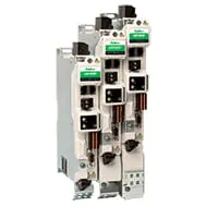
EtherCAT servo drives for the dual-motor bridge, carriage, tangential head and edge deletion axes.

Servo motors and sizing
Motor and gearbox selection from bridge mass, table size and cutting acceleration.
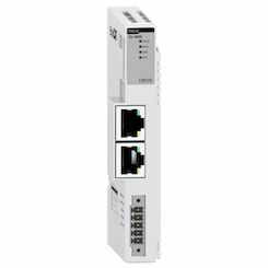
Remote I/O
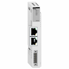
EtherCAT remote I/O for the cutting pressure valve, cutting oil, air cushion, reference sensors and safety signals.
Field reference
Motion control of the glass cutting table is built on the same CODESYS and X CNC path planning platform ONX Control uses in its CNC router and CNC cutting applications; field footage of those applications is on the CNC metal cutting page.
Retrofit scenario
A typical picture on older glass cutting tables: a closed CNC unit with no spare parts, a cutting head with manually set pressure and a control system that communicates poorly with the optimization software. In a retrofit the table, bridge and cutting head mechanics are usually kept; drives and control are renewed, cutting pressure is tied to the path and cut plans are loaded from file.
- Surveying bridge, carriage, cutting head and air cushion
- Servo sizing from bridge mass and target speeds
- Moving control to a CODESYS and X CNC Library architecture
- Setting up the cut plan file format and pressure recipes per glass type
- Verifying dimensions and breaking quality with test sheets
Frequently asked questions
Why is a tangential cutting head needed?
A cutting wheel only scores cleanly in the direction it rolls. In shape cutting the wheel has to turn as the path changes direction; the controller calculates this angle from the path and drives the C axis together with it.
Why does cutting pressure change along the path?
At the start and end of a cut, on tight curves and at corners, the same pressure can make breaking harder or cause chipping at the edge. Pressure comes from the recipe for glass thickness and is adjusted separately in these parts of the path.
How are cut plans transferred?
Straight cuts come from the optimization software's cut list, shaped parts as DXF or G-code. The file format and transfer method are agreed in the project.
Can coated and laminated glass be cut on the same table?
Coated glass needs an edge deletion axis; laminated glass needs extra equipment that scores both sides and heats the interlayer to separate it. These functions can be added to the same controller as extra axes and recipes.
What information is needed for a quote?
Table size, glass thickness range and types, target cutting speed, need for shape cutting, extra functions such as edge deletion and loading, the optimization software in use and the existing control system are enough for a first assessment.
Discuss your glass cutting machine with our engineers
Share your table size, glass types and cutting targets; we will come back with an axis layout, servo sizing and an architecture proposal.