
 Control Techniques
 Estun Automation
 CODESYS
 Crevis
 Nexcom / Nexcobot
 Leroy-Somer
 Servo Systems
 AC Drive + Motor
 DC Drives
 Smart PLC
 Panel PC / IPC
 Remote I/O
Press Brake Axis Control: Servo-Hydraulic and Electric
By the ONX Control engineering team · Last updated:
In short
A press brake forms sheet metal by bending it between an upper and a lower die. The bend angle is set by how deep the ram enters the lower die, so the axes at both ends of the ram (Y1 and Y2) have to be positioned precisely and kept parallel. On hydraulic press brakes this is done with proportional valves or servo pumps; on electric press brakes directly with servo motors. ONX Control builds ram, back gauge and crowning control for press brake builders with servo drives, CODESYS and EtherCAT.
How it works
On a synchronized hydraulic press brake the ram is carried by two hydraulic cylinders, each with a linear scale measuring the ram position beside it. The controller runs separate position loops for the two axes and continuously corrects the difference between them, so the ram stays parallel even when the sheet is bent near one end (eccentric load). A cycle consists of rapid approach, change to bending speed at the speed change point, bending, decompression and return.
In a classic hydraulic circuit a fixed-speed motor runs the pump continuously and motion is set with proportional valves. In a servo pump (servo-hydraulic) layout a servo motor drives the pump: ram speed and direction are set by pump speed, and the pump stops while the ram waits. This lowers energy consumption, oil heating and noise, especially during idle time. Electric press brakes have no hydraulics; the ram is driven by servo motors through ball screws or pulley-and-belt systems.
Bend depth is calculated from material thickness, tensile strength, lower die V opening, tool dimensions and springback. The back gauge axes (X, R, Z1, Z2) set the position of the sheet relative to the die and move as servo axes to a new position for every bend step. On long parts the ram and bed deflect under load, changing the angle in the middle; a crowning system compensates by bending the bed upward in proportion to the load.
-
1
Rapid approach
The ram travels quickly down to the speed change point just above the sheet.
-
2
Bending
The ram switches to bending speed; Y1 and Y2 move synchronously to the calculated depth, with a short dwell if needed.
-
3
Decompression and return
Cylinder pressure is released in a controlled way and the ram returns to the top; the sheet springs back.
-
4
Back gauge
The back gauge axes move to the position for the next bend and the program steps on.
Critical parameters
| Parameter | Why it matters | Typical range / ONX field data |
|---|---|---|
| Press force and bed length | Set cylinder bore and hydraulic pressure, or motor torque on an electric drive. | Defined per project |
| Ram speeds (approach, bending, return) | Set pump flow or servo motor speed and the cycle time. | Defined per project |
| Position repeatability | Depends on scale resolution, valve or pump dynamics and control loop cycle time; sets bend angle repeatability. | Defined per project |
| Y1/Y2 parallelism | Shows how quickly the difference between the two cylinders is corrected under eccentric load. | Defined per project |
| Number and speed of back gauge axes | X, R, Z1, Z2 and extra axes as part complexity requires; directly affects cycle time. | Defined per project |
| Drive type | Proportional valve hydraulics, servo pump hydraulics or electric; sets the balance of energy use, maintenance and cost. | Defined per project |
ONX architecture
In the ONX architecture ram, back gauge and crowning axes are brought together in one controller running CODESYS. Linear scales, servo drives and remote I/O connect over EtherCAT; Y1/Y2 synchronization, bend depth calculation and bend programs run in the controller. With servo pumps each cylinder's pump is driven as a separate servo axis; with proportional valves the valve references come from analog outputs. Bend programs and the tool library are managed from the operator panel.
A press brake is a machine where the operator works close to the tools. Safety functions such as laser guarding, two-hand control, safe speed and safe stop are built with a safety controller and the drives' safety functions according to the machine builder's risk assessment and the relevant standard (EN 12622 for hydraulic press brakes).

CODESYS
Y1/Y2 synchronization, back gauge axes, bend depth calculation and bend programs.

Industrial PC and panel
Panel PC running the controller, bend program editor and tool library.
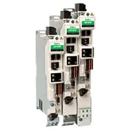
Servo drives
EtherCAT servo drives for servo pumps, electric ram and back gauge axes.
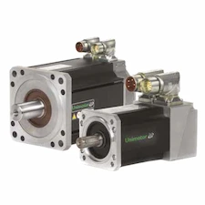
Servo motors and sizing
High-torque servo motors for the pump or ram drive, low-inertia motors for the back gauge.
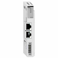
Remote I/O
EtherCAT remote I/O for scales and pressure sensors, valves, foot pedal and safety signals.
Field reference
The architecture on this page is built on the same CODESYS, EtherCAT and servo drive platform ONX Control uses in its flying punch, cut-to-length and CNC applications. We work out the axis layout and drive selection for your machine together in a meeting.
Retrofit scenario
A typical picture on older press brakes: mechanical or torsion-bar synchronization, manually set stroke and an old NC control unit with no spare parts. In a retrofit the frame, cylinders and tools are usually kept; linear scales, a proportional valve or servo pump group, a servo back gauge and a new control system are added. These steps can be done together or in stages, depending on the machine's condition.
- Surveying frame, cylinders, hydraulic unit and the existing synchronization
- Choosing the drive type: proportional valve, servo pump or keeping the existing unit
- Mounting scales and renewing the back gauge axes with servos
- Rebuilding safety functions with a risk assessment
- Verifying angle and parallelism with test bends
Frequently asked questions
How does a servo pump press brake differ from a proportional valve press brake?
In a proportional valve circuit the pump runs continuously at fixed speed and motion is set by throttling with the valve. In a servo pump circuit pump speed sets ram speed and direction, and the pump stops when the ram stops. As a result energy use, oil heating and noise drop during idle time.
How are Y1 and Y2 kept parallel?
Each cylinder's position is measured by its own linear scale and the two axes run separate position loops. The controller continuously watches and corrects the difference between them; under eccentric load one cylinder works harder but the ram stays parallel.
When is an electric press brake the better choice?
For short and medium bed lengths, high cycle rates and clean working environments; there is no hydraulic unit or oil maintenance. For high press forces and long beds hydraulic or servo-hydraulic layouts are more common.
Can our existing press brake be retrofitted?
Usually yes, if the frame and cylinders are sound. Scales, valve or servo pump group, back gauge and control system are renewed, and safety functions are rebuilt with a risk assessment.
What information is needed for a quote?
Press force and bed length, existing or target drive type, ram speeds, number of back gauge axes, sheet thicknesses and materials, and the existing control system are enough for a first assessment.
Discuss your press brake project with our engineers
Share press force, bed length, drive type and axis needs; we will come back with servo sizing and an architecture proposal.