
 Control Techniques
 Estun Automation
 CODESYS
 Crevis
 Nexcom / Nexcobot
 Leroy-Somer
 Servo Systems
 AC Drive + Motor
 DC Drives
 Smart PLC
 Panel PC / IPC
 Remote I/O
Assembly and Missing Part Verification
By the ONX Control engineering team · Last updated:
In short
Assembly verification is a system that uses camera images to check whether the components that should be on an assembled part (screws, clips, connectors, seals, labels, cables) are present, correctly oriented and of the right type. A missing or reversed part is rejected at the station before it reaches the customer. ONX Control builds this inspection with a Linux-based edge AI computer, a GigE camera and the station PLC; the result and image of every part are logged against its serial number.
How it works
When the part arrives at the station, the PLC triggers the camera. The model finds each component in the image individually and returns its position. The components found are then compared with the expected list in the recipe for that product variant: how many screws there should be, which slot the connector is in, what colour the seal is, which corner the label is on.
Rule-based image processing needs a separate tool and threshold for each component; these thresholds break down when the part colour, the lighting or the position of a cable changes. A deep learning model is more robust to this variability because it learns each component from examples seen at different angles and under different lighting. Position and orientation checks are then made on the coordinates returned by the model, using measurable rules.
The result goes back to the station as OK/NOK; on NOK, the location of the missing component is highlighted on the operator screen and the part is diverted to a reject chute, or the station waits for confirmation. The image, result and recipe of each part are logged with its serial number or part ID, providing retrospective evidence in the event of a customer complaint.
-
1
Trigger and image
When the part is seated, the PLC triggers the camera; if needed, several images are taken from different angles.
-
2
Component detection
The model finds each screw, connector, seal and label individually.
-
3
Recipe comparison
The components found are compared with the expected list for the product variant, using position and orientation rules.
-
4
Result and logging
OK/NOK goes to the PLC and NOK parts are rejected; the image and result are logged with the part ID.
Critical parameters
| Parameter | Why it matters | Value |
|---|---|---|
| Number of product variants | Determines recipe management and how many different appearances the model has to learn. | Defined per project |
| Components to be checked | The size and visibility of each component determine the number of cameras, their angle and the resolution. | Defined per project |
| Station cycle time | Image acquisition, inference and the response to the PLC must all fit within this time. | Defined per project |
| Hidden surfaces | Components at the back or inside require a second camera, a mirror or an axis that turns the part. | Defined per project |
| Traceability requirement | Determines how long images are kept, at what resolution and which system they are linked to. | Defined per project |
Values are determined after reviewing your product and station; we do not make general accuracy or cycle time promises on this page.
ONX architecture
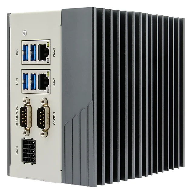
The camera and lighting are fixed at the station, and images reach the edge AI computer over GigE. On simple stations, the 4 digital inputs and 4 digital outputs of the Nexcom COEUS-3721T carry the trigger and OK/NOK signals directly; recipe selection and result data go to the PLC via Modbus TCP or OPC UA.
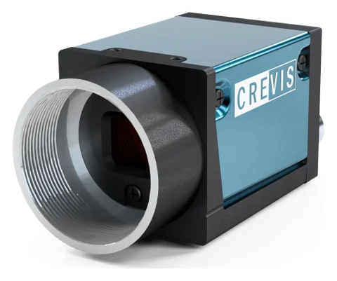
At assembly stations the part is usually stationary when the image is taken, so the rolling shutter Crevis MG-A121L-9 camera in stock (4024 × 3036) is well suited to this application. In a small cell, CODESYS Control for Linux ARM64 SL can also run as the station PLC on the same device.
GigE industrial camera and optics
Crevis MG series GigE Vision cameras and 12 MP lenses. Resolution, sensor type (rolling or global shutter), lens and lighting are selected according to the smallest defect and the line speed. The MG-A121L-9 (Sony STARVIS IMX226, rolling shutter + Global Reset) and MG-A121K-9 (Sony Pregius IMX304, global shutter) in stock are powered over PoE on a single cable and triggered from an encoder or photocell through their external trigger input.
Edge AI computer
Nexcom COEUS-3721T: fanless box PC, NVIDIA Jetson Orin Nano 4 GB (512-core Ampere GPU; manufacturer rating 34 TOPS, INT8, Super mode), 2 × GbE, 4 × USB 3.0, HDMI, 4 DI / 4 DO, RS232/422/485, CAN, 9–30 V DC, DIN rail. Models run on the GPU with TensorRT or ONNX Runtime under Ubuntu 22.04 and JetPack 6.2; images never leave the plant.
PLC and motion control
The decision goes to your existing PLC via a digital output, Modbus TCP or OPC UA. In small cells, CODESYS Control for Linux ARM64 SL can run as the PLC on the same Jetson device.
Image processing and model software
Image acquisition and pre-processing with Python and OpenCV, YOLO-family detection and segmentation models, labelling, training and model version control; the operator screen and logging interface are written by ONX.
Feasibility and pilot
What decides the success of an AI project is your product, your lighting and your line speed, not a catalogue figure. That is why every project starts with your own samples: first, images are collected on the bench with the right camera, lens and lighting, an initial model is trained, and the false reject and miss rates are measured on your parts. If the result meets the acceptance criterion, the system runs on the line as a pilot, initially in a mode that only logs and makes no decisions.
In assembly verification, during the pilot phase the system only logs for a period; the operator's inspection and the system's decision are compared side by side. Every part where they disagree is reviewed, and the model or rule is corrected if necessary. When a new product variant is added, the same step is repeated in shortened form.
Adding it to an existing line
Visual inspection is often added to an existing assembly line, replacing or supplementing the operator's visual check. Space is made at the station for the camera and lighting, trigger and result signals are added to the PLC, and the result and image are shown on the operator screen.
- Compiling the list of components to be checked, together with the product variants
- Trying out camera angle and lighting on the bench so that all components are visible
- Adding trigger, OK/NOK and recipe selection signals to the station PLC
- Designing the reject chute or operator confirmation flow
- Writing results and images to the MES or a database with the part ID
Together with ONX solutions
This application connects directly to the motion control of the machines and lines ONX builds. How the vision or data result feeds the PLC, servo axes and EtherCAT network in these solutions:
Packaging machines + OCR, code reading and rejection
Date, lot and DataMatrix prints are read at the packaging machine's outfeed, compared with the machine's active recipe, and faulty packs are rejected. On thermoformers and tray sealers, product presence and placement in each cavity can be checked before sealing. Reject timing is tied to the machine's master axis position, so the right pack is removed even when speed changes.
Press brake and tube bending + vision measurement
The bend angle of a formed part or the cross-section of a profile can be measured by camera, and the deviation is applied as a correction to the next part's axis target. On window machines, profile type, holes and fittings can be verified before processing.
Frequently asked questions
Can it replace the operator's visual inspection?
In repetitive, fast and tiring inspection, the camera looks at every part with the same attention and logs every result. During the pilot phase, the system's decision is compared with the operator's; the decision-making mode is enabled only after you have agreed with us on the result of this comparison.
If there are many product variants, is a new model needed for each?
Usually not. The model learns to recognise components (screws, connectors, seals); how many there should be and where, for each variant, is held in the recipe. A new variant can usually be added with a new recipe entry, whereas a new component type requires labelled examples.
Can it see components behind or inside the part?
The camera only checks what it can see. For hidden components, a second camera, a mirror or an axis that turns the part is added; sometimes it is better to move the check to an earlier assembly step.
Where are the results stored?
Images and results are stored with the part ID on a computer or server inside the plant. The retention period and MES integration are defined in the project; data is not sent to a cloud service.
Do we need to replace our existing PLC?
No. The edge computer passes the result to your existing PLC via digital output, Modbus TCP or OPC UA; trigger and result steps are added to the PLC program.
Let us talk about your assembly checklist
Share your product variants, the components to be checked and the station cycle time; we will draw up a feasibility plan with your samples.