
 Control Techniques
 Estun Automation
 CODESYS
 Crevis
 Nexcom / Nexcobot
 Leroy-Somer
 Servo Systems
 AC Drive + Motor
 DC Drives
 Smart PLC
 Panel PC / IPC
 Remote I/O
PVC and Aluminium Window Machine Automation
By the ONX Control engineering team · Last updated:
In short
PVC and aluminium window machines are the family of machines that turn 6-metre profile bars into window and door frames: a double mitre saw cuts the profile at an angle, a copy router or profile machining centre opens drainage slots and lock pockets, a four-head welder welds a PVC frame in one go and a corner cleaner removes the weld bead. What they have in common is positioning parts, whose sizes come from a cut list, quickly and repeatably with servo axes. ONX Control builds the control of these machines with CODESYS, EtherCAT and servo drives.
How it works
In window fabrication a window travels like this: window software produces the cut list and cutting optimisation from the order; the double mitre saw cuts the profiles to length at 45° or 90° and each part gets a barcode label; a machining centre or copy router opens drainage, handle and lock pockets; for PVC a four-head (or six- or eight-head) welder melts and joins the frame and sash with a heating plate and a CNC corner cleaner removes the weld bead with knives and cutters; for aluminium the corners are joined with a crimping press and corner cleats. Size errors travel down this chain: a millimetre error at the saw comes back as a frame diagonal and glazing problem at the welder.
On a double mitre saw one head is fixed and the other is moved to the cut length by a servo axis (ball screw or rack). Cut length comes from the cut list; the controller calculates head position from the angle, blade thickness and profile section. Saw feed can be pneumatic, hydraulic or servo; for aluminium the feed rate and blade speed are selected from a recipe by profile section. On automatic cutting centres the profile is pushed to the cut point by a feed carriage (servo pusher) and the parts are labelled and sorted; here cycle time is set by feed axis acceleration and cut time.
On a four-head welder the heads are positioned in X and Y to the frame size by servo; the heating plate moves in, the profile ends are melted for a set time and pressure, the plate moves out and the heads advance by the joining stroke to complete the weld. Frame diagonal and corner accuracy depend on head positioning repeatability and on an equal joining stroke; heater temperature is held by PID. After welding the frame moves on a conveyor to the corner cleaner, where X, Y and Z axes run the cleaning program from the profile library at each corner.
Profile machining centres process 6 to 12 metre bars with several axes (longitudinal X, Y, Z and a rotary A axis): drilling, slotting, lock pockets and end milling. Clamps move out of the tool path automatically during machining and the tool changer selects the tool from the recipe. The program comes from the window software and runs as G-code or a macro list; interpolation, velocity planning and tool compensation are the job of the CNC kernel.
-
1
Cut list
The order and optimisation list from the window software is loaded into the controller; every part's length, angles, profile and label are known.
-
2
Cutting and machining
The moving head or feed carriage travels to the cut length by servo; the machining centre opens slots and pockets from its program.
-
3
Welding
The welding heads are positioned to the frame size and heating and joining stroke run from the recipe.
-
4
Corner cleaning
The corner cleaning axes run the program from the profile library at each corner; the frame moves on to the next station.
Critical parameters
| Parameter | Why it matters | Typical range / ONX field data |
|---|---|---|
| Cut length tolerance | Sets the frame diagonal at welding and how the glass fits; assessed together with moving head positioning accuracy and blade compensation. | Defined per project |
| Cut angle and profile section | For mitre cuts the head position is calculated from profile section and angle; the accuracy of the profile library is critical. | Defined per project |
| Cycle time | Sets windows per day; feed and head axis acceleration, cut and weld times are assessed together. | Defined per project |
| Weld head repeatability | Frame diagonal and corner angle depend on head position and an equal joining stroke. | Defined per project |
| Profile library | Cut compensation, weld allowance and corner cleaning program per profile; grows as new profile systems are added. | Defined per project |
| Axis count and tool change | X/Y/Z/A axes, number of clamps and tool magazine on a machining centre set cycle time and investment. | Defined per project |
ONX architecture
In the ONX architecture the machine is controlled by CODESYS Control running on an industrial PC or panel PC. Head, feed and cleaning axes run on one time base with EtherCAT servo drives; saw and cutter motors run on AC drives and heater temperatures are held by PID. The cut list is taken from the window software as CSV, XML or over the network, and parts are tracked by barcode.
On profile machining centres and CNC corner cleaners, G-code, interpolation, look-ahead velocity planning and tool compensation are handled by X CNC Library; single-axis positioning by CODESYS SoftMotion. The profile library and recipes are managed from the operator screen; remote access for service and alarm history run on the same platform.

CODESYS and X CNC Library
Cut list, profile library, servo positioning; G-code and interpolation on machining centres and corner cleaners.

Panel PC
Panel PC running the cut list, barcode, recipes and operator screen.
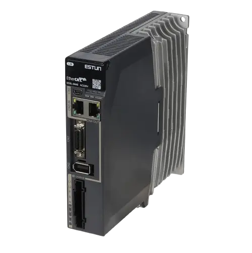
Servo drives
EtherCAT servo drives for the moving head, feed carriage, weld heads and cleaning axes.

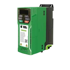
Servo motors and sizing
Motor and gearbox selection from head mass, stroke and acceleration target.
Field reference
The video below is field footage of a four-corner welding, robot and cleaning line from ONX Control's YouTube channel. We work out your machine's axis layout, cut list flow and profile library together in a meeting.

Retrofit scenario
A typical picture on window machines: a discontinued NC unit or closed PLC, servo drives with no spare parts, a profile library only the machine builder can change and a screen with no link to the window software, where sizes are typed in by hand. In a retrofit the head, welding and cleaning mechanics are kept; control moves to CODESYS, drives move to EtherCAT servos and the cut list is taken directly from the software.
- Surveying axis mechanics, existing motors and the profile library
- Re-sizing head and feed axes for the target cycle time
- Moving control to a CODESYS + EtherCAT architecture; transferring the profile library to an open format
- Setting up cut list and barcode flow from the window software
- Commissioning in a planned shutdown and size verification with sample frames
Frequently asked questions
Can the cut list be taken directly from the window software?
Yes. Most window software exports the cut list as CSV, XML or its own format; the controller reads it over the network or from USB. Each line holds profile code, length, angles, quantity and label data; the profile code is matched to the profile library in the controller.
How is the moving head position kept accurate?
It is positioned by the servo motor encoder and the mechanical ratio; the reference point is measured once, and blade thickness and mitre geometry are compensated in software. On long axes ball screw pitch error or rack backlash can be corrected with a compensation table.
What does a servo axis bring to a four-head welder?
When the heads are positioned to the frame size by servo, size changes come from the recipe, the joining stroke is applied equally at every head and frame diagonals are more consistent. On machines with pneumatic stops, sizes are set by hand and repeatability depends on the condition of the stops.
What does X CNC Library do on a profile machining centre?
It takes slotting and milling paths from G-code and runs them within axis limits with look-ahead velocity planning and corner smoothing. Repeated jobs such as drilling and lock pockets can be defined as macros.
What information is needed for a quote?
Machine type, number of axes and strokes, target cycle time, number of profile systems, the window software in use and the existing control system are enough for a first assessment.
Discuss your window machine control with our engineers
Share your machine type, axis layout and cycle target; we will come back with servo sizing and a control architecture proposal.