
 Control Techniques
 Estun Automation
 CODESYS
 Crevis
 Nexcom / Nexcobot
 Leroy-Somer
 Servo Systems
 AC Drive + Motor
 DC Drives
 Smart PLC
 Panel PC / IPC
 Remote I/O
AI-Based Surface Defect Detection
By the ONX Control engineering team · Last updated:
In short
Surface defect detection is a quality inspection system that automatically finds defects such as scratches, stains, holes and wrinkles on the surface of moving material (fabric, sheet metal, plastic film, paper, wood panels, concrete paving blocks) from camera images. Classical rule-based image processing struggles with patterned and textured surfaces; a deep learning model learns from defective and defect-free samples and can tell defects apart on these surfaces as well. ONX Control builds this system with a Linux-based edge AI computer, a GigE camera and the line encoder; the position of each defect is tracked along the line, and the decision to mark, reject or stop the line goes to the PLC.
How it works
In surface inspection, lighting matters more than the model. Scratches on bright sheet metal become visible with low-angle (dark-field) lighting, holes in film and fabric with backlighting, and stains with diffuse front lighting. The camera is triggered by the line encoder: an area-scan camera captures a frame every time the material advances by a set distance, and overlapping frames cover the entire surface. On wide lines, several cameras are mounted side by side.
The model is built in one of two ways. If the defect classes are known and there are enough examples of each, a YOLO-family detection or segmentation model returns both the location and the type of the defect. If defects are rare and examples are scarce, an anomaly detection model that learns only from defect-free surfaces flags every region that deviates from the normal texture. The model runs on the GPU of the edge computer with TensorRT; the design requirement is that processing one frame takes less time than the interval between two camera triggers.
As soon as a defect is found in the image, it is matched to the encoder position. This way, when the defect reaches a marking head or reject point several metres downstream of the camera, it is marked in the right place. For each defect, the metre position, cross-web position, class and an image crop are logged; at the end of each roll or batch, a defect map and quality report are produced.
In concrete paving block and kerb production (vibro-press lines), inspection takes place right after the press, while the product is still wet: as the pallet leaves the press for the curing chamber, the camera looks at the top face of every block and finds broken corners, cracks, incomplete filling, surface voids and defects in the coloured face mix. Because the wet surface is shiny and its tone changes as it dries, lighting geometry and a model trained on your own products are decisive here. Results are logged against the pallet number and shown to the operator in real time; the defect trend reveals a drift in filling, vibration or mix before the whole batch is affected. Product height is measured at the same station with a laser line and a camera.
-
1
Image acquisition
The camera is triggered by the line encoder; with the right lighting, the whole surface is scanned without gaps.
-
2
Pre-processing
Frames are split into tiles suited to the model, and brightness and perspective are corrected.
-
3
Inference
The model on the GPU finds the location and class of the defect, or flags the region that deviates from normal.
-
4
Decision and logging
The defect is tracked by the encoder; marking, rejection or a stop command goes to the PLC, and the defect map is saved.
Critical parameters
| Parameter | Why it matters | Value |
|---|---|---|
| Line speed and material width | Determine the number of cameras, the trigger interval and how quickly each frame must be processed. | Defined per project |
| Smallest defect size | Determines the required resolution (mm/pixel): the smallest defect must cover several pixels in the image. | Defined per project |
| Surface type | Bright, matt, patterned or transparent surfaces determine the lighting geometry and camera angle. | Defined per project |
| Defect classes and number of samples | Determines whether a classification model or an anomaly model trained only on defect-free surfaces is used. | Defined per project |
| Acceptance criterion | The balance between false rejects and missed defects, agreed with you according to the value of the product and the consequence of the defect. | Defined per project |
These values are determined in a feasibility study with your samples. We do not make general speed or accuracy promises without seeing the product and the lighting conditions.
ONX architecture
The camera image reaches the edge AI computer over GigE. The Nexcom COEUS-3721T we hold in stock runs Ubuntu-based JetPack Linux on an NVIDIA Jetson Orin Nano 4 GB module; the model runs on the GPU with TensorRT. The decision goes to the line PLC either directly through the device's digital outputs or via Modbus TCP and OPC UA; the line encoder and the marking unit are handled on the PLC side.
Camera selection depends on line speed. The Crevis MG-A121L-9 in stock (4024 × 3036, colour, 1/1.7 in) has a rolling shutter sensor with a Global Reset mode: it gives good results on stationary or slow-moving surfaces, and on moving surfaces when Global Reset mode is combined with short strobe lighting. For fast-moving material, the global shutter MG-A121K-9 in stock (Sony Pregius IMX304, 4112 × 3008) or a line-scan camera is selected; wide, fast lines need an edge PC with a more powerful GPU.
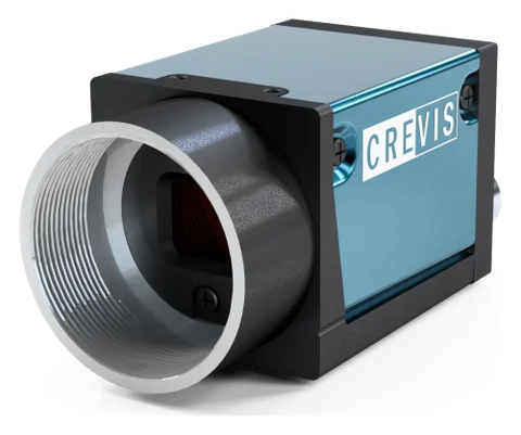
GigE industrial camera and optics
Crevis MG series GigE Vision cameras and 12 MP lenses. Resolution, sensor type (rolling or global shutter), lens and lighting are selected according to the smallest defect and the line speed. The MG-A121L-9 (Sony STARVIS IMX226, rolling shutter + Global Reset) and MG-A121K-9 (Sony Pregius IMX304, global shutter) in stock are powered over PoE on a single cable and triggered from an encoder or photocell through their external trigger input.
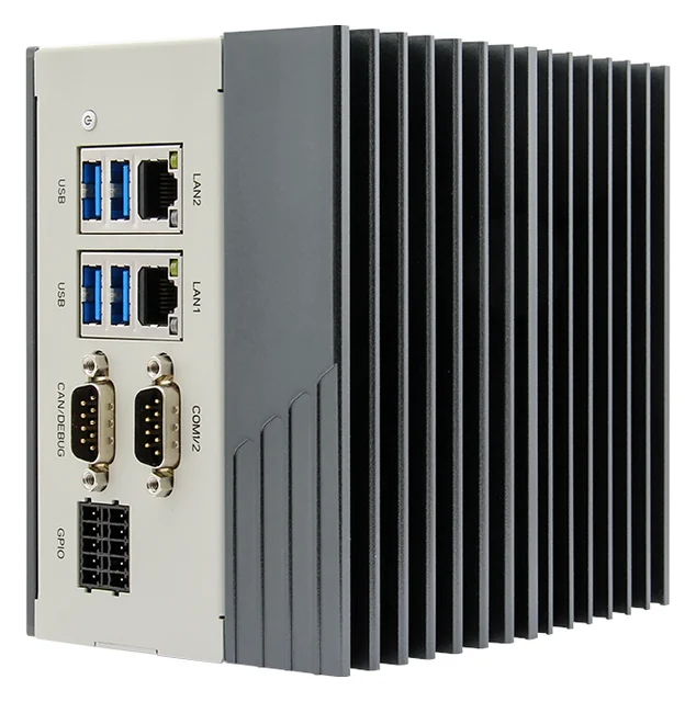
Edge AI computer
Nexcom COEUS-3721T: fanless box PC, NVIDIA Jetson Orin Nano 4 GB (512-core Ampere GPU; manufacturer rating 34 TOPS, INT8, Super mode), 2 × GbE, 4 × USB 3.0, HDMI, 4 DI / 4 DO, RS232/422/485, CAN, 9–30 V DC, DIN rail. Models run on the GPU with TensorRT or ONNX Runtime under Ubuntu 22.04 and JetPack 6.2; images never leave the plant.
PLC and motion control
The decision goes to your existing PLC via a digital output, Modbus TCP or OPC UA. In small cells, CODESYS Control for Linux ARM64 SL can run as the PLC on the same Jetson device.
Image processing and model software
Image acquisition and pre-processing with Python and OpenCV, YOLO-family detection and segmentation models, labelling, training and model version control; the operator screen and logging interface are written by ONX.
Feasibility and pilot
What decides the success of an AI project is your product, your lighting and your line speed, not a catalogue figure. That is why every project starts with your own samples: first, images are collected on the bench with the right camera, lens and lighting, an initial model is trained, and the false reject and miss rates are measured on your parts. If the result meets the acceptance criterion, the system runs on the line as a pilot, initially in a mode that only logs and makes no decisions.
In surface inspection, during the pilot phase, images captured at the real line speed and under the real lighting are labelled and added to the model; reflections, dust and roll splices that are not seen on the bench come to light at this stage. The defect map is compared with the defects found manually by your quality team; the decision-making mode is enabled once this comparison is complete.
Adding it to an existing line
A surface inspection system is usually added to a running line. The camera and lighting are mounted on a bridge, the line encoder signal is shared, and a few signals are added to the existing PLC for marking or rejection. The changes to the line's control software are minor.
- On-site assessment of space, vibration and ambient light for the camera bridge
- Taking a position signal from the line encoder or adding a measuring wheel
- Connecting the marking head, reject flap or stop signal to the PLC
- Pilot in log-only mode first, then switching to decision-making mode
- Transferring the defect map to production and quality systems
Together with ONX solutions
This application connects directly to the motion control of the machines and lines ONX builds. How the vision or data result feeds the PLC, servo axes and EtherCAT network in these solutions:
Winding, slitting and extrusion + surface defect detection
Defects on film, foil, paper or strip are recorded on the same position axis as the winder's metre counter and the line encoder. Each reel's defect map is therefore stored together with its tension and speed log, and the cause (tension swings, a splice, the die) can be traced on one timeline. On a slitting line the defective section can be removed at the reel change.
Textile and sewing automation + vision
Defects in fabric and yarn can be found by camera while the material moves. In pocket setting and sewing automation the fabric edge, pattern or mark is located by camera and the servo axes' stitch path is corrected to the part's real position, within the same ONX motion application and without a separate vision controller.
Frequently asked questions
Classical image processing or deep learning?
If the surface is uniform and defect contrast is high, rule-based image processing may be sufficient; it is simpler and easier to explain, and in that case we recommend it. Deep learning is needed on variable surfaces such as patterned fabric, wood grain or textured sheet, and wherever a defect is hard to define.
How many samples are needed?
A model that distinguishes defect classes needs examples of each class; if defects are rare, you can start with an anomaly detection approach that learns only from defect-free surfaces. The actual number depends on the surface and the defect, and is determined with your samples in the feasibility study.
Do the images go to the cloud?
No. The model runs on the edge computer beside the line; images and logs stay on your plant network, and the system works without an internet connection.
How do you mark a defect without stopping the line?
The defect is matched to the encoder position at the moment it is found in the image. As the material advances, its position is tracked, and the defect is marked or rejected when it reaches the marking head or reject point; every defect is also written to the defect map.
Can defects be detected on wet concrete paving blocks?
Yes. Inspection takes place right after the pallet leaves the press, before it enters the curing chamber. Because the wet surface is shiny and its tone changes as it dries, lighting and camera angle are chosen accordingly and the model is trained on your own good and defective blocks. Seeing the defect right at the press outlet keeps the same problem from spreading through a whole batch; product height can be measured at the same station with a laser line.
What happens if a new type of defect appears?
The system logs suspicious images. The new defect type is labelled and added to the dataset, and the model is retrained; every model version is recorded, and you can roll back to a previous version if necessary.
Let us test your surface defects with your samples
Material type, line speed and width, smallest defect size and a few defective samples are all we need; we will come back to you with a feasibility plan.