
 Control Techniques
 Estun Automation
 CODESYS
 Crevis
 Nexcom / Nexcobot
 Leroy-Somer
 Servo Systems
 AC Drive + Motor
 DC Drives
 Smart PLC
 Panel PC / IPC
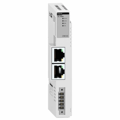 Remote I/O
Roll Forming Line Automation
By the ONX Control engineering team · Last updated:
In short
A roll forming line forms strip uncoiled from a coil step by step through a series of roll stands and produces profiles, panels or roof and wall elements at the required length. The line usually combines punching and notching, forming and cut-off; the length and hole pattern of every part come from the production list. ONX Control builds feed, punching, cut-off and main drive control for roll forming lines in one controller with CODESYS SoftMotion, EtherCAT, servo and AC drives.
How it works
The typical order is: uncoiler, straightener, punching and notching stations, forming stands, cut-off and runout table or stacker. Punching is done in one of two ways: with pre-punching a servo feeder indexes the strip into the press and the press hits while the strip is stopped, and a loop pit absorbs the speed difference to the continuous forming section; with a flying punch the press rides on a carriage with the strip and punches without stopping the line.
There are three cut-off strategies. Stop-to-cut lines slow down and stop for every cut; the design is simple but throughput drops on short parts. Pre-cut lines cut the strip flat before forming; no profile-specific die is needed, but part ends can flare in forming and gaps form between parts. Post-cut flying lines cut the formed profile with a profile-matching die or a saw on a carriage synchronized to line speed; since the line never stops, this gives the highest throughput.
Because holes are positioned relative to part length, punching and cutting must share the same measurement. The controller tracks every part along the line using the position from the measuring wheel or the servo feeder: several parts can be between the punch station and the cut-off. The next order's hole pattern can then start before the current order's last cut, with no scrap at the order change.
The forming section is usually driven by one or more AC motors through a gearbox or chain. On flying cut-off and flying punch lines the main drive sets line speed and the cut and punch axes follow it. On stop-to-cut lines the main drive has to stop quickly and at the same position for every cut, so closed-loop vector control with an encoder is used.
-
1
Uncoiling and straightening
The uncoiler pays out strip under tension or loop control; the straightener removes coil set.
-
2
Punching and notching
With a servo feeder and pre-punch press or a flying punch, the hole pattern from the production list is punched into the strip.
-
3
Forming
Roll stands bring the strip step by step to the profile section; the main drive sets line speed.
-
4
Cut-off and stacking
The profile is cut to length by stop-to-cut or flying cut-off and passed to the runout table or stacker.
Critical parameters
| Parameter | Why it matters | Typical range / ONX field data |
|---|---|---|
| Line speed | Sets the sync speed of flying cut-off and flying punch carriages, or the stop-start time per cut on stop-to-cut lines. | Defined per project |
| Strip thickness and material | Set forming power, press force and the cut-off method. | Defined per project |
| Part length range | The shortest length is limited by cut cycle and carriage stroke; decides between stop-to-cut and flying cut-off. | Defined per project |
| Hole pattern and density | Sets press strokes per minute and whether pre-punching or a flying punch is used. | Defined per project |
| Length and hole position tolerance | Depends on measuring wheel slip, encoder resolution and whether punching and cutting share the same measurement. | Defined per project |
| Production list | Parts per order, length and hole pattern; sets scrap at order changes and the need for part tracking. | Defined per project |
ONX architecture
In the ONX architecture the servo feeder, flying punch and flying cut-off axes and the forming main drive are brought together in one controller running CODESYS SoftMotion on CODESYS Control RTE on an industrial PC. The measuring encoder, servo and AC drives and remote I/O share one time base over EtherCAT; the punch and cut carriages are coupled to the measuring axis with electronic cams.
Part tracking, hole patterns and the production list run in the same controller; the list is entered from the operator panel and every part's length, hole pattern and quantity are stored with the recipe. The uncoiler's tension or loop control follows the same line speed reference.

CODESYS SoftMotion
Servo feeder, flying punch and flying cut-off axes; electronic cams, part tracking and production list.

Industrial PC
Industrial PC or panel PC running CODESYS Control RTE, the production list and the line screen.
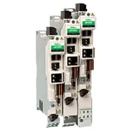
Servo drives
EtherCAT servo drives for the servo feeder and punch and cut carriages.

Main drive
AC drive and motor with encoder for the forming section; fast, positioned stops on stop-to-cut lines.
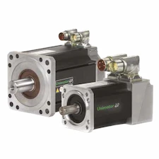
Servo motors and sizing
Motor and gearbox selection from carriage mass, stroke and feed profile.
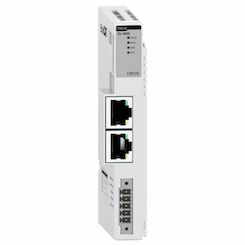
Remote I/O
EtherCAT remote I/O for press and cut valves, loop sensors, stacker and safety signals.
Field reference
The punching and cut-off axes of a roll forming line are built on the same synchronization platform ONX Control uses in its flying saw, flying punch and cut-to-length applications; field footage of those applications is on the related solution pages.
Retrofit scenario
A typical picture on older roll forming lines: a contactor-switched main motor, cut-off triggered by a limit switch, a fixed-die punch press and part length set by hand for every order. In a retrofit the roll stands and dies are usually kept; the main drive moves to an AC drive with encoder, a measuring wheel is added, cut-off and if needed punching are converted to servo or flying operation, and the production list moves to the panel.
- Mapping the line order, cut-off and punching methods and target speed
- Moving the main drive to an AC drive with encoder and adding a measuring wheel
- Assessing a move from stop-to-cut to flying cut-off against speed and length range
- Moving hole patterns and the production list to the panel and part tracking to the controller
- Commissioning tests with order changes and short parts
Frequently asked questions
Stop-to-cut or flying cut-off?
Stop-to-cut is simpler and cheaper and is enough for long parts and low speeds. On short parts the stop-start for every cut lowers throughput; a flying cut-off that cuts without stopping the line is then preferred. The decision depends on line speed, part length mix and profile section.
Pre-punching or flying punch?
With pre-punching a servo feeder indexes the strip into the press; hole position is very precise, but a loop pit is needed before the continuous forming section. A flying punch punches without stopping the line and makes the line shorter; as hole density rises, carriage dynamics become the limit.
Why is there scrap at an order change?
The strip between the punch station and the cut-off belongs to the following parts. If the controller does not track parts along the line, this section has to be run out and scrapped at an order change. With part tracking the next order's hole pattern can start before the current order's last cut.
How is the distance between holes and cut kept accurate?
Punching and cut-off are coupled to the same measuring axis and every part is tracked in the controller with one position reference. Measuring wheel slip is the most important factor in the accuracy of this distance.
What information is needed for a quote?
Profile type and section, strip thickness and material, line speed, part length range, hole patterns, the existing cut-off and punching method and the control system are enough for a first assessment.
Discuss your roll forming line with our engineers
Share your profile, speed target, part lengths and hole patterns; we will come back with a cut-off and punching method, servo sizing and an architecture proposal.