Cut-to-Length Line Automation
In short
A cut-to-length line is a stop-and-go system that indexes sheet or strip uncoiled from a coil by a set length with feed rolls, stops it, and cuts it with a stationary shear or saw while the material is at rest. Cut length accuracy depends on the positioning accuracy of the feed axis, slip between the rolls and the material, and the measuring method. ONX Control builds these lines with CODESYS SoftMotion, EtherCAT and servo drives, managing feed positioning with the motor encoder and, where needed, a measuring wheel running on the material.
How it works
On a typical sheet cut-to-length line, material from the decoiler passes through a straightener (leveller) and then over a loop pit to the servo-driven feed rolls. The decoiler and straightener run continuously while the feed rolls run stop-and-go; the loop absorbs the speed difference between the two sections, and a loop sensor adjusts the straightener speed.
In each cycle the feed axis makes a relative move equal to the cut length, stops, and the shear or saw completes the cut. Because the cut length is simply a servo position, it is set from the recipe. Move time depends on the cut length and axis dynamics: if the axis cannot reach top speed the time is roughly t = 2·√(L/a), otherwise t = L/v + v/a. Acceleration therefore governs the cycle on short lengths, and feed speed on long lengths.
-
1
Feed
The servo feed rolls advance the material by the cut length; an S-curve (jerk-limited) profile reduces slip between rolls and material.
-
2
Stop and position check
The axis stops on target; if a measuring wheel is fitted, the actual material travel is read and a small correction move is made if needed.
-
3
Cut
The shear, guillotine or saw cuts while the material is stopped; feeding stays interlocked until the cut is confirmed.
-
4
Stacking and counting
The cut part is transferred to the stacker; part count and batch completion are shown on the operator panel.
Critical parameters
| Parameter | Why it matters | Typical range / ONX field data |
|---|---|---|
| Feed speed | Sets cycle time on long lengths; the loop pit size and straightener speed must match it. | Defined per project |
| Cut length tolerance | The sum of positioning error, roll slip, roll diameter wear and measuring encoder resolution. | Defined per project |
| Cycle rate (cuts per minute) | The sum of feed move, settling time and shear stroke time; on short lengths acceleration and shear time dominate. | Defined per project |
| Material thickness, width and coil weight | Determine roll pressure, feed motor torque and the power of the decoiler drive. | Defined per project |
| Cut length range | The shortest length sets the cycle time; the longest sets feed speed and loop capacity. | Defined per project |
ONX architecture
In the ONX architecture, the feed axis is driven by CODESYS SoftMotion running on CODESYS Control RTE, using PLCopen relative positioning blocks. The measuring wheel is read over EtherCAT as a separate encoder axis; the motor encoder closes the speed and position loops, while the measuring wheel verifies actual material travel and compensates for slip.
Decoiler and straightener drives run in speed control on AC drives and speed up or slow down according to the loop sensor. Cut lists, batch quantities and calibration factors are managed from the operator panel.

CODESYS SoftMotion
Relative positioning, measuring wheel axis, slip compensation and cut list management.

Industrial PC
Industrial PC running CODESYS Control RTE and the operator screen.
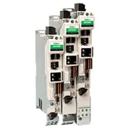
Feed servo drive and motor
EtherCAT servo drive for the feed rolls; motor and gearbox sized for roll inertia and material mass.

Decoiler and straightener drives
AC drives and induction motors in speed control, following the loop sensor.
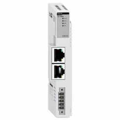
Remote I/O
EtherCAT remote I/O for shear and guillotine valves, loop sensor, material-end and safety signals.
Field reference
The images below are principle illustrations of the stop-and-go cut-to-length cycle and a servo feed roll arrangement.
Principle illustrations


Retrofit scenario
A typical picture on older cut-to-length lines: feeding with a brake motor and an encoder counter, where length error varies with speed, or a mechanical length stop that needs adjustment at every length change. In a retrofit the decoiler, straightener and shear are usually kept; the feed drive moves to a servo and the control moves to CODESYS.
- Measuring feed roll diameter, roll pressure mechanism and the existing drive train
- Sizing servo motor and gearbox for the target cycle rate and length range
- Adding a measuring wheel on the material where needed
- Moving the control to a CODESYS SoftMotion + EtherCAT architecture and transferring cut lists to the panel
- Calibration by cutting and measuring samples at different lengths
Frequently asked questions
What is the difference between a cut-to-length line and a flying shear?
On a cut-to-length line the material stops for every cut and a stationary shear cuts it; with a flying shear the line never stops and the cutter travels with the material while cutting. The stop-and-go design is mechanically simpler and suits precise lengths. A flying shear is preferred when a continuous process runs upstream (such as a tube or profile mill) or high line speed is required.
Measuring wheel or motor encoder?
The motor encoder measures the rotation of the feed roll; with roll slip or roll diameter wear, actual material travel differs from it. A measuring wheel in contact with the material measures actual travel, but it must itself be correctly loaded and placed so it does not slip. Precise applications use both: the motor encoder for the control loop and the measuring wheel for correction.
How is roll slip compensated?
The difference between the measuring wheel and the motor encoder is measured every cycle; after the stop, the remaining error to target is closed with a small correction move or added to the next feed target. A jerk-limited profile and correct roll pressure also reduce the slip itself.
What limits the cycle rate on short lengths?
On short lengths the axis usually starts decelerating before it reaches top speed, so time is set by acceleration and shear stroke time. For a higher cycle rate, motor and gearbox must be sized with an acceleration target based on roll and material inertia.
What information is needed for a quote?
Material type, thickness and width range, coil weight, cut length range, required tolerance and cycle rate, shear or saw type and the existing control system are enough for a first assessment.
Discuss your cut-to-length line with our engineers
Share your material, cut length range, tolerance and cycle rate targets; we will come back with feed axis sizing and an architecture proposal.