CNC Metal Cutting Control (Plasma, Laser, Oxy-Fuel, Router)
In short
CNC metal cutting control moves the axes of a gantry carrying a plasma, laser, oxy-fuel or router head together along the contour defined in a G-code program, so the sheet is cut to the required shape. The controller interprets the G-code, generates position setpoints for every axis in each cycle through linear and circular interpolation, and uses look-ahead to plan speed ahead of corners and short segments. ONX Control builds this control on a PC-based platform with CODESYS SoftMotion CNC, EtherCAT and servo drives.
How it works
The part is drawn and nested in CAD/CAM software, and the CAM output is G-code based on DIN 66025. The controller reads the program line by line, turns each line into a geometric path element such as a line, arc or helix, and separates process commands such as torch on/off and pierce delay as M functions.
Path elements are not sent straight to the axes; they first pass through look-ahead preprocessing. By examining the segments ahead, the controller builds a speed profile that keeps every axis within its velocity, acceleration and jerk limits at corners and in runs of short segments, and smooths corners where allowed. The interpolator then splits this path into position setpoints for X, Y and Z every task cycle, so the axes move in step while the contour speed is held constant.
-
1
Loading the G-code
The CAM program is selected on the operator panel; the sheet origin and, if needed, the sheet skew angle are set.
-
2
Interpretation and path preprocessing
G-code is converted into path elements; look-ahead plans the speed profile, and corner smoothing and kerf compensation are applied.
-
3
Interpolation and motion
The interpolator generates axis setpoints every cycle; servo drives follow them over EtherCAT on a common time base.
-
4
Process control
Torch ignition, pierce delay, torch height control and end-of-cut are executed as M functions, synchronized with the motion.
Critical parameters
| Parameter | Why it matters | Typical range / ONX field data |
|---|---|---|
| Cutting speed and rapid travel speed | Cutting speed comes from material, thickness and cutting process; rapid (G0) speed is limited by gantry mass and drive mechanics. Together they set the time per part. | Defined per project |
| Contour accuracy | The sum of axis following error, the difference between the two gantry sides, mechanical backlash and kerf compensation; it shows most at corners and small circles. | Defined per project |
| Cycle rate (parts per hour, pierce count) | The sum of cut length, rapid moves and the dwell at every pierce; on parts with many holes, pierce time becomes dominant. | Defined per project |
| Axis acceleration and jerk | Determine how much look-ahead must slow down at corners; high acceleration excites gantry vibration, low acceleration slows corners excessively. | Defined per project |
| Gantry mass and drive mechanics | Rack and pinion, ball screw or belt; determine servo motor torque and gear ratio. | Defined per project |
ONX architecture
In the ONX architecture, G-code interpretation, look-ahead and interpolation run in CODESYS SoftMotion CNC inside CODESYS Control RTE on an industrial PC; no separate CNC control unit is needed. Servo drives and remote I/O connect over EtherCAT and run on a common time base through EtherCAT Distributed Clocks.
On a dual-motor gantry axis both sides follow the same setpoint; the gantry is squared during homing and the position difference between the sides is monitored during operation. Torch height control, cutting parameter tables and the operator screen live in the same CODESYS project, so process-specific functions can be added without depending on a closed CNC.

CODESYS SoftMotion CNC
G-code interpreter, look-ahead path preprocessing, linear/circular interpolation and M functions.

Industrial PC
Industrial PC or panel PC running CODESYS Control RTE and the operator screen.
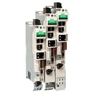
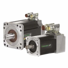
Servo motors and sizing
Motor and gearbox selection based on gantry mass, target acceleration and drive mechanics.
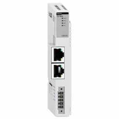
Remote I/O
EtherCAT remote I/O for torch ignition, arc OK, height sensor, limit and safety signals.
Field reference
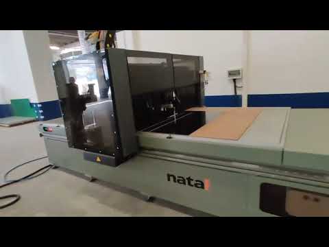
The videos below are field footage of CNC router applications from ONX Control's YouTube channel: the axes are driven from G-code by interpolation in CODESYS SoftMotion CNC. Plasma, laser and oxy-fuel cutting gantries use the same control architecture; what changes are the process functions of the cutting head.

Principle illustrations
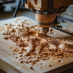
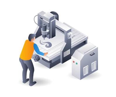
Retrofit scenario
A typical picture on older cutting machines: a closed CNC unit with no spare parts left, axes driven by an analog reference or stepper motors, and software that cannot reliably read current CAM output. In a retrofit the gantry, rails and cutting source (plasma power unit, laser source) are usually kept; the control, drives and, if needed, motors are replaced.
- Measuring gantry mass, drive mechanics, rails and gantry squareness
- Reviewing existing G-code programs and the CAM post-processor output
- Moving the control to a CODESYS SoftMotion CNC + EtherCAT architecture
- Connecting torch height control and the cutting source interface to the new control
- Commissioning with test cuts from existing programs
Frequently asked questions
Why is look-ahead needed?
Without look-ahead the controller either has to stop at the end of every segment or enters corners faster than the axes can follow. Planning the speed profile ahead keeps contour speed as high as possible while slowing the axes within their limits at corners, which directly affects cut surface and corner quality.
Which CAM software does it work with?
CODESYS SoftMotion CNC reads G-code based on DIN 66025. Any CAM software whose post-processor output follows this structure can be used; process-specific M functions are defined together during the project.
How are the two gantry motors kept in sync?
Both motors follow the same position setpoint, each with its own position loop. The gantry is squared during homing, the difference between the two sides is monitored during operation, and motion is stopped if it exceeds a limit.
How is torch height controlled in plasma cutting?
In plasma cutting the Z axis is usually corrected from the measured arc voltage. Because arc voltage changes when speed drops at corners and small holes, height correction is frozen in those zones. Laser heads use capacitive distance sensing instead.
What information is needed for a quote?
Cutting process (plasma, laser, oxy-fuel, router), table size, gantry mass and drive mechanics, target cutting and rapid speeds, the CAM software in use and the existing control system are enough for a first assessment.
Discuss your CNC cutting project with our engineers
Share your cutting process, table size and speed targets; we will come back with axis sizing and an architecture proposal.