
 Control Techniques
 Estun Automation
 CODESYS
 Crevis
 Nexcom / Nexcobot
 Leroy-Somer
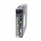 Servo Systems
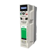 AC Drive + Motor
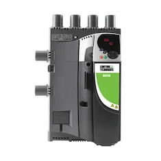 DC Drives
 Smart PLC
 Panel PC / IPC
 Remote I/O
Wood Spray Painting CNC Machine Automation
By the ONX Control engineering team · Last updated:
In short
A wood spray painting CNC machine paints panels, kitchen doors, MDF and furniture parts with spray guns moving on a gantry. The controller recognizes the shape and position of the part, generates the painting path for faces and edges, moves the gun along that path at constant speed and switches the gun on and off at the part edges based on position. Even film thickness depends on a constant path speed and on gun triggering being synchronized with motion. ONX Control builds this control with CODESYS, EtherCAT and servo drives, using ONX's X CNC path planning library.
How it works
On a typical machine the parts enter the spray booth on a conveyor or table. The gantry moves in X and Y and the gun carrier in Z; to paint edges and profiled surfaces the gun is angled with a rotation (C) and a tilt (A) axis. The part's shape and position are read by a scanner, light curtain or camera at the infeed, or taken from the part program (DXF).
The controller generates the painting path from the part contour itself. For the face, the gun travels back and forth over the part in parallel stripes; stripe spacing is chosen from the spray fan width with a given overlap. For the edges, the gun follows the contour at a set distance, angled towards the edge. If path speed drops at corners and short segments, paint builds up there; the path is therefore generated with look-ahead velocity planning and corner smoothing.
The gun opens and closes by position, not by time: it opens a set distance before the part edge and closes after passing it. The gun valve's opening and closing delay multiplied by path speed is used to move the trigger position ahead, so paint starts at the part edge even when speed changes. Film thickness is set by paint flow, path speed and stripe spacing and is stored as a recipe per paint and part type.
Depending on the paint and ventilation, an explosive atmosphere zone can form in the spray booth. Motors, sensors and electrical equipment in this zone are chosen for the zone (ATEX) or placed outside it; ventilation and booth doors are interlocked with machine motion.
-
1
Part recognition
The part's shape, size and position are read by a scanner or taken from the part program.
-
2
Path generation
The face stripe pattern, angled edge path and gun on/off points are calculated automatically.
-
3
Painting
The gun moves along the path at constant speed and opens and closes by position; film thickness is held by the recipe.
-
4
Transfer and cleaning
The painted part moves to drying; a gun cleaning cycle runs at colour changes or at set intervals.
Critical parameters
| Parameter | Why it matters | Typical range / ONX field data |
|---|---|---|
| Path speed | Together with paint flow, sets film thickness; must stay constant at corners and on short segments. | Defined per project |
| Stripe spacing and overlap | Chosen from the spray fan width; sets thickness uniformity on the face and painting time. | Defined per project |
| Gun trigger delay | Valve open/close time multiplied by path speed gives the length of unpainted or overpainted edge; compensated by moving the trigger position ahead. | Defined per project |
| Part size and thickness | Set gantry stroke and Z axis, edge painting angle and the conveyor or table layout. | Defined per project |
| Number of axes | Gun rotation and tilt axes in addition to X, Y, Z; set the ability to paint edges and profiles. | Defined per project |
| Paint type and number of guns | Water or solvent based paint, number of guns and colour changes; set the cleaning cycle and the zone class of booth equipment. | Defined per project |
ONX architecture
In the ONX architecture part recognition, path generation and motion control are brought together in CODESYS running on an industrial PC. Path planning and interpolation are done by ONX's X CNC Library: it merges short segments within a contour tolerance, smooths corners and plans velocity against axis dynamics; the gun rotation and tilt axes are smoothed together with the path. Servo drives and remote I/O share one time base over EtherCAT.
Gun valves are triggered by fast outputs tied to axis position; trigger delay compensation and film thickness recipes live in the same controller. Conveyor, transfer to drying, cleaning cycle and booth interlocks are managed in the same CODESYS project.

X CNC Library
Path planning, corner smoothing, look-ahead velocity planning and smoothing of rotary axes.

Industrial PC
Industrial PC or panel PC running CODESYS, part recognition and the recipe screen.

Servo motors and sizing
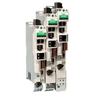
Motor selection from gantry mass, acceleration at stripe reversals and the gun axes.

Booth equipment
AC drives for fans, conveyor and pumps; ATEX motors for the explosive atmosphere zone.
Remote I/O
EtherCAT remote I/O for gun valves, part scanner, booth doors and ventilation signals.
Field reference
Motion control of the painting machine is built on the same CODESYS and X CNC path planning platform ONX Control uses in its CNC router and 5-axis applications. We work out the axis layout and path strategy for your parts and paint together in a meeting.
Retrofit scenario
A typical picture on older painting machines: a reciprocator moving back and forth with a fixed stroke, guns switching on and off regardless of part shape, and paint building up at corners. In a retrofit the booth, conveyor and guns are usually kept; motion moves to servo axes, a part scanner is added at the infeed, and path generation and gun triggering move into the controller.
- Surveying booth, conveyor, guns and the explosive atmosphere zone layout
- Deciding the axis layout and sizing the servo motors
- Choosing the part recognition method: scanner, light curtain or part program
- Setting up path generation, gun triggering and film thickness recipes
- Film thickness measurement and tuning with test parts
Frequently asked questions
Does every part need its own program?
No. When the part shape is read by a scanner at the infeed or taken from the part program, the face and edge paths are generated automatically in the controller from the stripe spacing, edge distance and gun angle in the recipe.
Why does paint build up at corners, and how is it prevented?
Path speed drops at a corner while the gun keeps spraying at the same flow. The path is generated with look-ahead velocity planning and corners are smoothed within the contour tolerance; if needed the gun is throttled or closed where the path slows down.
How are edges painted?
The gun is angled towards the edge with the rotation and tilt axes and follows the contour at a set distance. On profiled doors the profile area can be painted in a separate pass.
Can servo motors be used in a spray booth?
Motors can be placed outside the explosive atmosphere zone, or certified equipment suitable for the zone is chosen. The choice depends on the booth's zone class and the machine builder's risk assessment.
What information is needed for a quote?
Part types and dimensions, paint type, number of guns, target capacity, the required axis layout (edge and profile painting), booth layout and the existing control system are enough for a first assessment.
Discuss your painting machine with our engineers
Share your parts, paint and capacity target; we will come back with an axis layout, path strategy and architecture proposal.