
 Control Techniques
 Estun Automation
 CODESYS
 Crevis
 Nexcom / Nexcobot
 Leroy-Somer
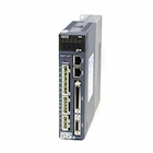 Servo Systems
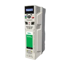 AC Drive + Motor
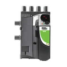 DC Drives
 Smart PLC
 Panel PC / IPC
 Remote I/O
Textile Yarn and Package Winding Machine Automation
By the ONX Control engineering team · Last updated:
In short
On electronic textile machines (fancy/effect yarn, twisting and package winding machines) the feed rollers, spindles and traverse guide are no longer driven by a common shaft, gearbox and mechanical cam; each has its own motor and drive and runs in sync with a master axis in software. Effect pattern, twist (turns per metre) and winding geometry are changed from the recipe, with no gear or cam change. ONX Control builds this architecture for textile machine builders with servo and AC drives, CODESYS SoftMotion and EtherCAT.
How it works
On a fancy (effect) yarn machine the effect comes from changing feed roller speeds. The core yarn is fed at constant speed while the roller feeding the effect yarn briefly speeds up or slows down according to the pattern; the overfed yarn forms effects such as slub (flamme), knop or bouclé. On an electronic machine the pattern is defined as effect length, effect thickness (speed ratio) and distance between effects, and turned into a speed profile for the servo axis. The pattern can be a fixed sequence or random within set limits; a random pattern prevents a regularly repeating mark in the fabric.
Twist is the ratio of spindle speed to yarn delivery speed: twist (turns/m) = spindle speed (rpm) / delivery speed (m/min). On a mechanical machine this ratio is set by change gears; on an electronic machine the spindle and the delivery roller are coupled to the same master axis with an electronic gear, so twist stays constant while the machine accelerates, decelerates and stops. On hollow-spindle fancy twisting machines the binder yarn's wraps per metre are set by the same ratio.
In package winding the traverse guide moves the yarn back and forth across the package to build a cross-wound package. The guide is coupled to the package spindle with an electronic cam: the cam profile defines the reversal at the stroke ends and the acceleration there; the reversal points are shifted slightly from stroke to stroke so that the package edges are neither hard nor bulging. Precision winding keeps the ratio between package turns and double strokes (wind ratio) constant; random winding keeps the crossing angle constant, so the ratio changes as the diameter grows. When the ratio passes certain values the yarn stacks on itself (ribbon formation); to prevent this the traverse speed is varied around those values. Step precision winding combines both: the ratio is held constant and switched to the next ratio when the crossing angle leaves its band.
Two layouts are common on multi-position machines. With group drive, the spindles on one side of the machine are driven by one motor through a tangential belt or line shaft, and the traverse guides by one servo motor through a common traverse rod running along the machine; the mass and elasticity of the rod then limit the acceleration at the reversal points. With individual drive each position has its own motors and a yarn break stops only that position. In both layouts all axes follow the same master axis, so ratios are kept while the machine accelerates, decelerates or stops.
-
1
Master axis and recipe
Machine speed is a virtual master axis; twist, effect pattern, wind ratio and package dimensions come from the recipe.
-
2
Feed and effect
Feed rollers follow the master with a speed ratio; the effect roller speeds up and slows down along the pattern profile.
-
3
Twist and winding
An electronic gear keeps the spindle-to-delivery ratio (twist); an electronic cam keeps the winding geometry of package spindle and traverse.
-
4
Synchronized stop
On a yarn break, a normal stop or a mains failure, all axes slow down together while keeping their ratios.
Critical parameters
| Parameter | Why it matters | Typical range / ONX field data |
|---|---|---|
| Yarn speed (m/min) | Sets delivery roller and package spindle speeds and the traverse double strokes per minute. | Defined per project |
| Twist range (turns/m) | Sets the top spindle speed and the choice of spindle drive. | Defined per project |
| Effect pattern | The shortest effect length and the highest speed ratio set the effect roller's acceleration and the servo motor's peak torque. | Defined per project |
| Traverse stroke and double strokes per minute | The acceleration at the reversal points, together with guide or traverse rod mass, sets servo sizing. | Defined per project |
| Winding type and wind ratio | Precision, step precision or random winding; sets package density and suitability for dyeing or the next process. | Defined per project |
| Number of positions and drive layout | Group or individual drive; sets the number of axes, EtherCAT cycle time and panel layout. | Defined per project |
| Package diameter and weight | Set the speed range of the package spindle and the inertia load of a full package. | Defined per project |
ONX architecture
In the ONX architecture machine speed is a virtual master axis in CODESYS SoftMotion running on CODESYS Control RTE on an industrial PC. Feed and effect rollers, spindles, package spindles and traverse are coupled to it with electronic gears or cams; the effect pattern and the traverse cam profile are calculated in the controller and reloaded on the fly when the recipe changes. Servo drives and remote I/O share one time base over EtherCAT.
Axes that need fast, precise motion (effect roller, traverse) use servo drives and servo motors; axes with high power but slowly changing speed (spindle group, main drive, fans and suction) use AC drives and induction motors, which follow the same master speed reference. On a mains failure the drives' DC bus is fed by the kinetic energy of the motors and all axes are brought to a controlled stop while keeping their ratios; how long this takes depends on machine inertia.

CODESYS SoftMotion
Virtual master axis, electronic gears and cams; calculation of the effect pattern and traverse profile.
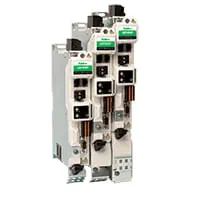
Servo drives
EtherCAT servo drives for dynamic axes such as the effect roller and traverse.

Servo motors and sizing
Motor and gearbox selection from traverse reversal acceleration and the peak torque of the effect pattern.
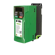
AC drives and motors
AC drives and induction motors for the spindle group, main drive, fans and suction.
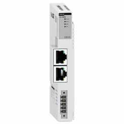
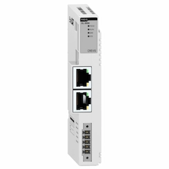
Remote I/O
EtherCAT remote I/O for yarn break sensors, position buttons, full-package and door signals.
Field reference
Textile machine builders are one of the main industries ONX Control supplies with servo systems, AC drives and control components. We share application examples close to your machine, and our proposed axis layout, in a meeting.
Retrofit scenario
A typical picture on older textile machines: motion distributed from one main motor through gearboxes and belts, change gears for pattern and twist, a mechanical cam box for the traverse and an old control board with no spare parts. Changing pattern or twist means changing gears and stopping the machine. In a retrofit the machine frame, spindles and rollers are usually kept; mechanical links are removed, the relevant axes get servo or AC drives, and pattern, twist and winding settings move into recipes.
- Mapping the machine kinematics: which shaft runs at which ratio, gear and cam values
- Choosing the axes to electrify and sizing servo / AC drives
- Turning existing pattern, twist and winding settings into recipes
- Yarn break, single-position stop and synchronized stop on mains failure
- Trial on one position first, then commissioning of the whole machine
Frequently asked questions
How is the effect pattern defined on an electronic fancy yarn machine?
The pattern is entered as effect length, effect thickness (the effect roller's speed ratio to the core yarn) and distance between effects. The controller turns these values into a speed profile for the effect roller. Values can be a fixed sequence or chosen randomly within set limits; changing the pattern needs no gear change.
Mechanical or electronic cam for the traverse?
A mechanical cam is made for one stroke and one reversal profile; changing them means changing parts. With an electronic cam, stroke, wind ratio and reversal profile come from the recipe; stroke shifting, step precision winding and ribbon breaking are done in software. The limit is the mass of the guide or common traverse rod and the acceleration at the reversal points.
Which axes should be servo and which AC drive?
Axes whose speed and position change quickly (effect roller, traverse, the delivery roller if needed) are servo; axes with high power but slowly changing speed (spindle group, main drive, fans and suction) run on AC drives. The final choice comes from sizing against the motion profile.
Does the yarn break on a power cut?
On a mains failure the drives can use the motors' kinetic energy on the DC bus for a controlled stop; because all axes follow the same master, they slow down together and keep their ratios. How quickly the machine can stop depends on its inertia and drive layout.
What information is needed for a quote?
Machine type, number of positions, yarn speed and twist range, effect pattern examples, traverse stroke and target package dimensions, the existing drive layout (group or individual) and, if available, the machine's kinematic diagram are enough for a first assessment.
Discuss your textile machine's drive architecture with our engineers
Share the machine type, number of positions, speed and pattern targets; we will come back with an axis layout, servo and AC drive selection and a control architecture proposal.