Flying Punch / Flying Press Automation
In short
A flying punch (flying press) punches holes, notches or forms into continuously moving sheet, strip or profile without stopping the line. The press or punching die sits on a carriage that moves synchronized to the speed read from a line encoder, so the relative speed between carriage and material is zero while the die is in contact. ONX Control builds this motion with a CODESYS SoftMotion electronic cam, EtherCAT and servo drives, and manages hole patterns and press timing in the same controller.
How it works
A measuring wheel on the line measures the position and speed of the material and serves as the master axis. The servo axis carrying the press carriage is coupled to this master by an electronic cam: the carriage accelerates from its waiting position, catches line speed, the press strikes in the synchronous zone, and the carriage then decelerates and returns. Unlike a flying shear, it can make many strikes at varying intervals along a single part.
The length of the synchronous zone depends on die contact time and line speed: s ≥ v × t (contact). On a hydraulic press the stroke time can vary with oil temperature and pressure, so the synchronous zone is set for the longest time and synchronization is released on confirmation from a bottom dead centre or die-up sensor. On a servo press the ram is also an axis, so the stroke profile and contact time are set in software. For thin strip with a single repeating pattern, a rotary punch running on rotating drums, similar to a rotary knife, can also be used.
-
1
Pattern and queuing
Hole positions along the part and tool selection are read from the recipe; a target position on the line encoder is queued for every strike.
-
2
Catch and synchronous zone
As the target approaches, the carriage accelerates to line speed and relative speed drops to zero.
-
3
Press stroke
The press is triggered in the synchronous zone; synchronization is held until the die is confirmed clear of the material.
-
4
Return
The carriage returns in time for the next strike. When holes are close together, it can catch the next hole without returning to its start position.
Critical parameters
| Parameter | Why it matters | Typical range / ONX field data |
|---|---|---|
| Line speed | Sets the carriage synchronous speed, the synchronous zone length and the servo motor power. | Defined per project |
| Hole position tolerance | The sum of measuring wheel slip, encoder resolution, synchronization following error and press trigger delay. | Defined per project |
| Cycle rate (strikes per minute) | Set by the spacing between consecutive holes and line speed; acceleration, synchronous and return times must fit into that interval. | Defined per project |
| Press contact time and type | The stroke time and its variation for a hydraulic, mechanical or servo press determine the required synchronous zone length. | Defined per project |
| Carriage mass and stroke | If the die and press frame travel with the carriage, mass grows; determines motor torque, gearbox and drive mechanics. | Defined per project |
ONX architecture
In the ONX architecture, the carriage axis is coupled to the line encoder by an electronic cam in CODESYS SoftMotion running on CODESYS Control RTE on an industrial PC. The line encoder, servo drives and the remote I/O carrying press valve and tool selector signals share one EtherCAT network on a common time base through Distributed Clocks, so the press trigger instant is based on material position.
Hole patterns and tool selection are stored as recipes. If the same line also has a flying shear, punching and cutting share the same line encoder, so holes are positioned relative to the cut point and the whole control runs in one CODESYS project.

CODESYS SoftMotion
Electronic cam (MC_CamIn), strike position queue and press trigger logic.

Industrial PC
Industrial PC or panel PC running CODESYS Control RTE and the recipe screen.
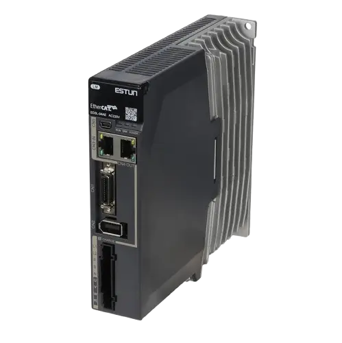
Servo drives
EtherCAT servo drives for the carriage and, where used, the servo press axis.

Servo motors and sizing
Motor and gearbox selection from carriage and die mass, stroke and strike spacing.
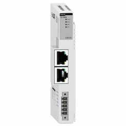
Remote I/O
EtherCAT remote I/O for press valves, tool selectors, bottom dead centre / die-up sensors and safety signals.
Field reference
The image below is a principle illustration of synchronized punching on moving material.
Principle illustrations

Retrofit scenario
A typical picture on existing punching lines: a stop-and-go design that halts the material for every hole, hole positions set with mechanical stops, or an old motion controller with no spare parts. The press and dies are usually kept; the carriage is converted to a servo drive, a line encoder is added and hole patterns are moved into recipes.
- Measuring press type, stroke and contact time, and the variation of that time
- Servo sizing based on carriage mass, stroke and drive mechanics
- Adding a line encoder (measuring wheel) and press position sensors
- Moving the control to a CODESYS SoftMotion + EtherCAT architecture and transferring patterns to recipes
- Commissioning with sample punching and position measurement at different line speeds
Frequently asked questions
What is the difference between a flying punch and a flying shear?
The motion principle is the same: the carriage synchronizes to line speed and the operation happens in the synchronous zone. A flying shear makes one cut per part; a flying punch can make many strikes at varying intervals along a part, with different tools for different holes. Queuing strike positions and tool selection are therefore a key part of flying punch control.
Can a hydraulic press be used for flying punching?
Yes. Because a hydraulic press stroke time can vary, the synchronous zone is set for the longest contact time and synchronization is released on confirmation from a sensor that the die has cleared the material. If a shorter, more repeatable contact time is needed, a servo press is considered.
What happens if holes are very close together?
If the distance between two strikes is not enough for acceleration, synchronous and return times, the profile is calculated so the carriage catches the next hole without returning to its start position. If that is still not enough, either line speed is reduced or the holes are punched in the same stroke with several punches in the die.
How are holes aligned to the cut point?
Punching and cutting share the same line encoder, and hole positions are defined relative to the cut point. Because the controller knows the distance between press and shear, every hole and cut is made in the same material coordinate.
What information is needed for a quote?
Material and cross-section, line speed range, hole patterns and number of tools, press type and contact time, carriage and die mass, required position tolerance and the existing control system are enough for a first assessment.
Discuss your flying punch project with our engineers
Share your line speed, hole patterns and press data; we will come back with a synchronous zone calculation, servo sizing and an architecture proposal.