
 Control Techniques
 Estun Automation
 CODESYS
 Crevis
 Nexcom / Nexcobot
 Leroy-Somer
 Servo Systems
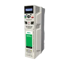 AC Drive + Motor
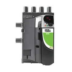 DC Drives
 Smart PLC
 Panel PC / IPC
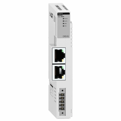 Remote I/O
CNC Tube Bending Machine Automation
By the ONX Control engineering team · Last updated:
In short
A CNC tube bending machine turns straight tube into a three-dimensional part by feeding, rotating and bending it in sequence. Each bend is defined by three values: the straight length between bends (Y), the plane of the bend (B) and the bend angle (C). On all-electric machines all of these axes and the pressure die booster are driven by servo motors; bending speed, sequence and springback compensation are set in software. ONX Control builds tube bender control with CODESYS SoftMotion, EtherCAT and servo drives.
How it works
In the common rotary draw bending method the tube is clamped between the bend die and the clamp die, and the bend die rotates, drawing the tube around itself. The pressure die supports the outside of the tube; a mandrel inside the tube prevents ovality and a wiper die prevents wrinkling on the inside. For thin walls or tight radii the pressure die pushes the tube into the bend with a booster axis; this axis is coupled to the bend axis with an electronic gear so that push speed changes together with bend speed.
Part drawings usually come as the corner points of the tube centreline (XYZ coordinates). The controller converts them, taking the bend radius into account, into a YBC table: feed length, rotation angle and bend angle for each bend. After bending the tube springs back a little and elongates in the bend zone, so an overbend depending on the material is added to C and an elongation correction to Y. Correction values are measured with test bends and stored as tables per material and tool.
On older machines the bend is usually made by a hydraulic cylinder and rack, with B and Y driven by separate hydraulic or induction motors. In an all-electric layout every axis is servo, so bend speed can change along the bend (slow start, fast middle, slow finish), axes can move simultaneously to shorten the cycle, and positions are more repeatable. Bend sequence and B rotations are checked in the program so that the bent part does not hit the machine or the floor.
-
1
Feed (Y)
The carriage pushes the tube forward to the start of the next bend; the mandrel holds its position inside the tube.
-
2
Rotation (B)
The tube is rotated to the plane of the bend; some machines feed and rotate at the same time.
-
3
Clamping and bending (C)
Clamp and pressure dies close, the bend die rotates to the target angle plus springback allowance, and the booster pushes in sync with the bend.
-
4
Release and return
The dies open, the mandrel retracts if needed, the bend die returns to start and the program continues with the next bend.
Critical parameters
| Parameter | Why it matters | Typical range / ONX field data |
|---|---|---|
| Tube diameter and wall thickness | Set bending torque, tool dimensions and the need for a mandrel. | Defined per project |
| Bend radius and wall factor | The ratio of radius to diameter and of diameter to wall; sets the need for mandrel, wiper and booster, and the achievable bend quality. | Defined per project |
| Bend angle tolerance | Depends on the accuracy of the springback table, C-axis repeatability and variation between material batches. | Defined per project |
| Tube length and Y stroke | Set the longest part that can be bent in one clamping and the carriage drive mechanics. | Defined per project |
| Number of axes and tool stacks | Booster, tool stack change and left/right bending axes in addition to Y, B, C; set the control architecture and cycle time. | Defined per project |
| Cycle time | Depends on axis speeds and accelerations and on which moves can be made simultaneously. | Defined per project |
ONX architecture
In the ONX architecture the Y, B, C and booster axes are controlled by CODESYS SoftMotion running on CODESYS Control RTE on an industrial PC; servo drives and remote I/O share one time base over EtherCAT. The booster follows the bend axis with an electronic gear; XYZ to YBC conversion and the springback and elongation tables run in the controller.
Hydraulic or pneumatic functions such as clamp, pressure die and mandrel are driven by valves through remote I/O, or as servo axes where needed. Part programs are managed as recipes from the operator panel; for every part the bend list, tooling and material are stored together.

CODESYS SoftMotion
Y, B, C and booster axes; electronic gear, XYZ → YBC conversion and springback tables.

Industrial PC
Industrial PC or panel PC running CODESYS Control RTE, part programs and the operator screen.
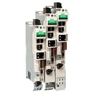
Servo drives
EtherCAT servo drives for feed, rotation, bend and booster axes.
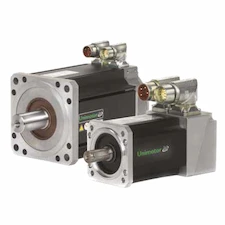
Servo motors and sizing
Motor and gearbox selection from bending torque, carriage mass and rotation inertia.
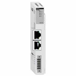
Remote I/O
EtherCAT remote I/O for clamp, pressure die and mandrel valves, tube sensors and safety signals.
Field reference
The video below is field footage of a fully automatic tube bending application from ONX Control's YouTube channel: a CODESYS-based, servo-driven tube bender making recipe-based 3D bends.
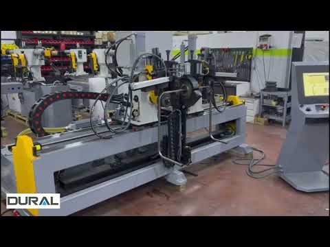
Retrofit scenario
A typical picture on older tube benders: bending by hydraulic cylinder, axes with encoders but driven through analog valves, springback corrected by hand for every batch, and an old NC control unit with no spare parts. In a retrofit the frame, tool sets and carriage mechanics are usually kept; the axes move to servo drives, control moves to CODESYS and part programs are transferred to the new recipe structure.
- Surveying existing axes, tool sets and hydraulic functions
- Sizing servo motors and gearboxes from bending torque and motion profile
- Moving control to a CODESYS SoftMotion + EtherCAT architecture
- Transferring part programs and springback values to the new recipe structure
- Verifying angles and lengths with test bends
Frequently asked questions
What is YBC?
The bend list of a tube part: feed length (Y), rotation angle (B) and bend angle (C) for each bend. It is calculated in the controller from the XYZ corner points of the drawing, taking the bend radius into account.
How is springback compensated?
Springback measured with test bends per material and tool is added to the target angle as overbend; elongation in the bend zone is corrected in the Y length. The values are stored as tables and can be updated for different material batches.
What is the difference between hydraulic and servo bending?
In hydraulic bending speed and position are controlled by a valve and cylinder; oil temperature and pressure can affect repeatability. In servo bending the bend angle is the motor position itself, bend speed can change along the bend and the booster can be coupled to the bend with an electronic gear.
Can our existing machine be converted to servo?
Usually yes, if the frame and tool sets are sound. Servo motors are sized from bending torque, carriage mass and target cycle time; the hydraulic bend cylinder can be replaced by a geared servo drive or by servo pump hydraulics.
What information is needed for a quote?
Tube diameter and wall thickness range, materials, bend radii, longest tube length, number of axes, target cycle time, sample part drawings and the existing control system are enough for a first assessment.
Discuss your tube bending machine with our engineers
Share your tube sizes, sample parts and cycle target; we will come back with an axis layout, servo sizing and an architecture proposal.