
 Control Techniques
 Estun Automation
 CODESYS
 Crevis
 Nexcom / Nexcobot
 Leroy-Somer
 Servo Systems
 AC Drive + Motor
 DC Drives
 Smart PLC
 Panel PC / IPC
 Remote I/O
Vision-Guided Robots and Servo Axes: Conveyor Tracking
By the ONX Control engineering team · Last updated:
In short
Vision-guided robotics is a system that uses a camera to locate parts lying at random positions and angles on a conveyor or table and picks them with a robot or servo axes. The part's position and angle are converted from camera coordinates to robot coordinates; if the conveyor is moving, the part is tracked with the encoder and the robot picks it on the move. ONX Control builds this system with an edge AI computer, a GigE camera and EtherCAT servo axes under CODESYS SoftMotion.
How it works
The camera views a section of the conveyor upstream of the robot's working area. The model finds every part and returns its position (x, y) and rotation angle (θ); if parts overlap or touch each other, a segmentation model separates each one. Which parts can be picked and which will be skipped is also decided at this step.
Hand-eye calibration converts camera coordinates into robot or axis coordinates. The conveyor encoder value at the moment the image is taken is stored with the part; as the part advances, its position is calculated from the encoder. The motion controller catches up with the part through synchronised motion on the conveyor axis, rotates the gripper to the part's angle, picks the part and places it at the target. This is the two-dimensional equivalent of the electronic cam synchronisation used in a flying shear.
This setup can be built with an off-the-shelf robot or with Cartesian (gantry) or SCARA-type servo axes built by ONX. When built with servo axes, vision, conveyor tracking and motion are combined in a single CODESYS SoftMotion application; drives, encoder and I/O operate on the same time base over EtherCAT.
-
1
Image and encoder
The conveyor encoder value is recorded at the moment the camera is triggered.
-
2
Position and angle
The model finds the x, y and θ of every part; pickable parts are selected.
-
3
Coordinates and tracking
Camera coordinates are converted to robot coordinates; the part is tracked with the encoder.
-
4
Synchronised picking
The axes synchronise with the conveyor, the gripper rotates to the angle, and the part is picked and placed.
Critical parameters
| Parameter | Why it matters | Value |
|---|---|---|
| Conveyor speed and part density | Determine how much time the robot has per part and how many robots or axis groups are needed. | Defined per project |
| Part size, shape and symmetry | Determine whether angle detection is needed, the gripper type and how demanding the model is. | Defined per project |
| Overlapping parts | Determines whether segmentation is needed and how skipped parts are returned. | Defined per project |
| Required placement accuracy | Determines camera resolution, calibration method and mechanical rigidity. | Defined per project |
| Robot or axis type | Off-the-shelf robot, Cartesian servo axes or SCARA; determines the integration method. | Defined per project |
Speed and accuracy depend on the mechanical design, the gripper and the part, and are calculated per project. We do not make general pick-and-place rate promises on this page.
ONX architecture
The camera image reaches the edge AI computer over GigE; the detection and angle estimation model runs on the GPU. The part list (x, y, θ and encoder value) is sent to the motion controller. Motion control is handled on an industrial PC with CODESYS Control and SoftMotion; in small cells, CODESYS Control for Linux ARM64 SL can also run on the same Jetson device.
The conveyor encoder, servo drives and I/O are brought together on a single EtherCAT network. When an off-the-shelf robot is used, the part list is passed to the robot controller over an industrial network, and conveyor tracking is handled by the robot's own function.
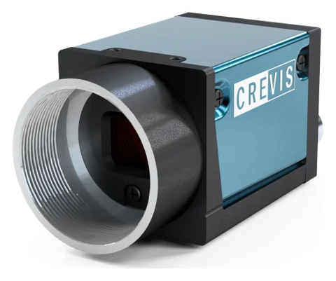
GigE industrial camera and optics
Crevis MG series GigE Vision cameras and 12 MP lenses. Resolution, sensor type (rolling or global shutter), lens and lighting are selected according to the smallest defect and the line speed. The MG-A121L-9 (Sony STARVIS IMX226, rolling shutter + Global Reset) and MG-A121K-9 (Sony Pregius IMX304, global shutter) in stock are powered over PoE on a single cable and triggered from an encoder or photocell through their external trigger input.
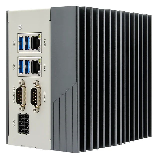
Edge AI computer
Nexcom COEUS-3721T: fanless box PC, NVIDIA Jetson Orin Nano 4 GB (512-core Ampere GPU; manufacturer rating 34 TOPS, INT8, Super mode), 2 × GbE, 4 × USB 3.0, HDMI, 4 DI / 4 DO, RS232/422/485, CAN, 9–30 V DC, DIN rail. Models run on the GPU with TensorRT or ONNX Runtime under Ubuntu 22.04 and JetPack 6.2; images never leave the plant.

Motion control
Synchronised motion on the conveyor axis with CODESYS SoftMotion, Cartesian and SCARA kinematics; the ONX X Motion library.
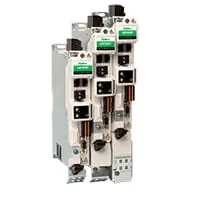
Servo drive and motor
Servo drives and motors with EtherCAT communication; sized according to axis mass and motion profile.
Feasibility and pilot
What decides the success of an AI project is your product, your lighting and your line speed, not a catalogue figure. That is why every project starts with your own samples: first, images are collected on the bench with the right camera, lens and lighting, an initial model is trained, and the false reject and miss rates are measured on your parts. If the result meets the acceptance criterion, the system runs on the line as a pilot, initially in a mode that only logs and makes no decisions.
In vision-guided picking projects, the feasibility study consists of two separate tests: whether your parts are correctly located in different positions, angles and pile-up situations, and measurement of placement accuracy with hand-eye calibration. Conveyor tracking is commissioned first with virtual axes, then on the real conveyor starting at low speed.
Adding it to an existing line
In manual stacking, case packing or feeding tasks, the existing conveyor is usually kept; the camera is installed above the conveyor, with the robot or axis group downstream of it. An encoder is fitted to the conveyor motor, or a separate measuring wheel is used.
- Measuring conveyor speed, part density and part variety
- Adding an encoder or measuring wheel to the conveyor
- Selecting and sizing the robot or servo axis group
- Hand-eye calibration between camera and robot
- Designing the return or reject path for parts that cannot be picked
Together with ONX solutions
This application connects directly to the motion control of the machines and lines ONX builds. How the vision or data result feeds the PLC, servo axes and EtherCAT network in these solutions:
Textile and sewing automation + vision
Defects in fabric and yarn can be found by camera while the material moves. In pocket setting and sewing automation the fabric edge, pattern or mark is located by camera and the servo axes' stitch path is corrected to the part's real position, within the same ONX motion application and without a separate vision controller.
Smart belt and lug chain infeed + camera
A camera placed instead of, or next to, the photocell gives the product's position, orientation and defects at once. The position feeds the phasing belt's correction; flipped, broken or incomplete products are rejected before they reach the wrapper. Since the smart belt already has encoders and servo axes, the vision result connects straight into motion control.
X CNC and CNC machines + camera-based alignment
The position and angle of a sheet or part placed anywhere on the table are found by camera and passed to X CNC Library's work coordinate system (origin and rotation), shortening manual referencing. On glass and wood, the sheet edge and defective areas can become inputs to the cutting or painting plan. The machined part's dimensions can be checked before it leaves the machine.
X Motion + conveyor-tracking pick
The x, y, θ from the camera and the encoder value at the moment of capture become a conveyor-tracking pick through X Motion's synchronisation and electronic cam functions. The Cartesian or SCARA axis group runs in the same CODESYS application, and the axes are sized with ONX Motion Sizing.
Robot cells and panels + zone monitoring
In cells built by ONX, the safety circuit is built separately in the panel with certified safety equipment. Camera zone monitoring can be added next to it as a warning and logging layer; it does not replace a safety function.
Frequently asked questions
Off-the-shelf robot or servo axes?
If flexible, multi-directional motion and a large working area are needed, an off-the-shelf robot; for uniform, highly repetitive tasks synchronised with a conveyor, Cartesian or SCARA servo axes can be simpler and more economical. The choice is made together, based on the part, the speed and the cell layout.
How are parts picked without stopping the conveyor?
The conveyor encoder is read at the moment the image is taken; the part's position is then continuously calculated from the encoder. The axes synchronise with the conveyor and pick while moving at the same speed as the part; the principle is the same as the synchronisation in a flying shear.
Can it distinguish overlapping parts?
A segmentation model can find parts that touch or partially overlap as separate objects. For parts piled completely on top of each other, it is usually more reliable to bring them down to a single layer with a mechanical spreader or vibratory feeder.
How is calibration done?
Hand-eye calibration is performed between the camera and the robot or axis coordinates: the robot moves to known points and the camera sees the same points. For conveyor tracking, the encoder scale and the distance between camera and robot are also calibrated.
How is the safety of the robot cell ensured?
Cell safety is implemented according to machine safety rules with fencing, safety light curtains, laser scanners and a safety PLC. The camera system is not a safety function.
Let us talk about your pick-and-place application
Sample parts, conveyor speed, target pattern and the current cell layout are all we need; we will propose an architecture with a robot or servo axis option.