
 Control Techniques
 Estun Automation
 CODESYS
 Crevis
 Nexcom / Nexcobot
 Leroy-Somer
 Servo Systems
 AC Drive + Motor
 DC Drives
 Smart PLC
 Panel PC / IPC
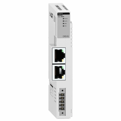 Remote I/O
Product Phasing into a Lug Chain (Flighted Infeed Synchronization)
By the ONX Control engineering team · Last updated:
In short
The infeed chain of flow wrappers, cartoners and similar machines carries products between lugs (flights, pushers) at a fixed pitch. Every product coming from the belt has to land between two lugs, without hitting a lug, and in the same position relative to the lug every time. Product phasing latches the edge of the product with a photocell, works out which lug it will go in front of, and changes the speed of the phasing belt so that the product is handed to the chain at exactly lug speed and in the right phase. The principle is similar to registration (print mark) control: the product edge takes the place of the print mark and the lug takes the place of the cut point. ONX Control builds this control in CODESYS SoftMotion, coupled to the master axis of the lug chain.
How it works
The lug chain is coupled to the machine's master axis; the chain position is known modulo the lug pitch and every gap between lugs is a slot. The instant the product passes the photocell on the phasing belt, the belt axis position is taken with the drive's fast latch input. From this measurement the controller works out when the product will reach the transfer point and which chain slot will be at the transfer point at that moment.
The difference between the product's arrival position and the position of the target slot is the phase error. While the product is on the belt, the phasing belt closes this error with an acceleration or deceleration move superimposed on the electronic gear, and returns to chain speed at the transfer. If the error is more than half a pitch, slowing down to the next slot is shorter than speeding up to the previous one; the controller picks the shorter correction. If the correction cannot be finished within the belt length, the slot is left empty.
Only one product may be on a phasing belt at a time; if products arrive close together, a gapping belt is needed first. The empty-slot information travels with the chain: on a flow wrapper the jaws do not make an empty pack in that gap. Because the correction is made against the master axis position, products stay in phase while the machine speeds up or slows down.
-
1
Measuring
The photocell sees the product edge; the phasing belt position is latched at that instant.
-
2
Slot assignment
The product's arrival time at the transfer point is calculated and the best free slot on the chain is chosen.
-
3
Phase correction
The phasing belt speeds the product up or slows it down to close the phase error against the target slot.
-
4
Transfer
The belt matches chain speed; the product lands in front of the lug in the same position every time.
Critical parameters
| Parameter | Why it matters | Typical range / ONX field data |
|---|---|---|
| Lug pitch and machine speed (products per minute) | Set the chain speed and the time left to measure and correct each product. | Defined per project |
| Phasing belt length | Sets the largest phase error that can be corrected on one product; if half a lug pitch can be corrected, every product finds a slot. | Defined per project |
| Friction between product and belt | Sets the highest acceleration the product allows without slipping; the correction profile is calculated within this limit. | Defined per project |
| Reference edge and product length tolerance | Products are placed by their leading edge, trailing edge or centre; length differences change when a pusher lug meets the product. | Defined per project |
| Latch accuracy | Photocell response time multiplied by belt speed gives the position uncertainty; for example, a 1 ms response at 1 m/s belt speed is about 1 mm. | Defined per project |
| Transfer geometry | The end of the phasing belt, the point where the lug rises from the chain sprocket and the gap between them decide that the product does not ride up on the lug. | Defined per project |
ONX architecture
In the ONX architecture the lug chain and the phasing belt are servo axes coupled to the same master axis in CODESYS SoftMotion running on CODESYS Control RTE on an industrial PC. The phasing belt follows the master through an electronic gear; the phase correction is added as a position move superimposed on that coupling, so whatever the machine speed, the belt is at chain speed at the transfer point.
The photocell connects to the drive's fast latch input or to a time-stamped EtherCAT input. The slot table, empty-slot information and reject logic run in the same controller and travel with the chain to the rotary jaws or the next station. Lug pitch, reference edge, target position and acceleration limit are managed as recipes from the operator panel.

CODESYS SoftMotion
Master axis, phasing belt electronic gear, superimposed phase correction and slot table.

Industrial PC
Industrial PC or panel PC running CODESYS Control RTE and the recipe screen.
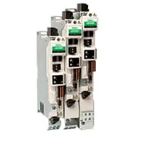
Servo drives
EtherCAT servo drives with fast latch inputs for the phasing belt and the lug chain.

Servo motors and sizing
Motor and gearbox selection from the accelerations and decelerations of the phase correction.
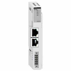
Remote I/O
EtherCAT remote I/O for photocells, slot occupancy sensor, reject device and safety.
Field reference
The video below shows ONX Control's 17-axis cake packaging line. Its infeed uses a smart belt and a lug chain: cakes coming from the servo belts are phased, placed between the lugs and carried to the packaging machine. All 17 servo motors are coupled to the same master axis and run in sync; the line was designed with Control Techniques drives and a CODESYS architecture.

Retrofit scenario
A typical picture on older machines: the lug chain and infeed belt driven from the same mechanical line shaft, with products brought to the lug by a pneumatic stop or by hand. When products arrive irregularly they ride up on the lug, slots stay empty or products are crushed. In a retrofit the chain and lugs are usually kept; the infeed belt becomes a servo phasing belt, a photocell is added and the chain and belt are coupled to the same master axis.
- Collecting lug pitch, product lengths and target products per minute
- Servo sizing from the phasing belt length and the acceleration limit
- Coupling the lug chain and the phasing belt to the same master axis
- Photocell, slot occupancy and empty-pack logic
- Commissioning with real product at different product lengths and speeds
Frequently asked questions
What is this called?
Placing products between lugs in phase is called "product phasing"; the infeed chain is called a "lug chain" or "flighted infeed", and the lug itself a "lug", "flight" or "pusher". Without lugs, the same job is done by a smart belt ("intelligent infeed").
How is it different from registration (print mark) control?
Both work on the same principle: a mark is latched by a photocell and the difference between measured and expected position is added to an axis as a phase correction. In registration control the mark is the print on the film and the correction goes to the jaws or the knife; in product phasing the mark is the product edge and the correction goes to the belt carrying the product.
What happens if a product arrives too early or too late?
The controller assigns the product to the previous or the next slot, whichever it can reach with the shorter correction. If the error is too large to close within the phasing belt, or two products are too close on the same belt, the slot is left empty, the product can be rejected if needed, and the empty slot is passed on to the machine.
Do products stay in phase while the lug chain speeds up or slows down?
Yes. Because the phasing belt is coupled to the master axis by an electronic gear, it speeds up and slows down with the chain; the phase correction is added on top of that coupling as a position. Only on very fast ramps is the acceleration limit checked so that products do not slip.
What information is needed for a quote?
Product dimensions and weight, lug pitch and chain design, target products per minute, how products arrive on the belt (spaced or touching), the packaging machine type and the existing drive system are enough for a first assessment.
Discuss your lug chain infeed with our engineers
Share your products, lug pitch and speed target; we will come back with a phasing belt calculation, servo sizing and an architecture proposal.