
 Control Techniques
 Estun Automation
 CODESYS
 Crevis
 Nexcom / Nexcobot
 Leroy-Somer
 Servo Systems
 AC Drive + Motor
 Smart PLC
 Panel PC / IPC
 Remote I/O
Wire Drawing Machine Automation
By the ONX Control engineering team · Last updated:
In short
A wire drawing machine thins wire rod or thick wire by pulling it through a series of dies. After each die the wire section gets smaller and, since volume is conserved, its speed rises by the same ratio; each drawing block therefore has to turn faster than the one before. If the speed difference between blocks is not exactly equal to the elongation ratio, the wire is either over-tensioned and breaks or piles up between blocks. ONX Control builds the block drives and spooler of wire drawing machines with CODESYS and AC drives, with dancer control between blocks.
How it works
On a straight-line wire drawing machine each block consists of a capstan, the motor driving it and a die box in front of it. The wire is pulled through the die, wraps a few turns around the capstan and moves on to the next die. Section ratio: speed of block n+1 = speed of block n × (d_n / d_n+1)². As dies wear and wire temperature changes, the real elongation drifts from the design value, so speeds have to be corrected by measurement, not only by calculation.
Small speed differences between blocks are sensed by dancers the wire runs through: the dancer is held against wire tension by a pneumatic cylinder or spring and its position is read by a potentiometer or encoder. The controller corrects each block's speed by PID to hold the dancer in its middle position. Usually the last block (or the spooler) is the line speed reference and, working backwards, each block is set from the next block's speed and its dancer. On accumulating machines without dancers the wire builds up on the capstan; this layout can mark the wire surface and cause tension ripple.
Wet (slip) drawing machines are used for fine copper and aluminium wire; all steps turn from one motor through gears and the wire slips over the steps. On these machines control focuses on the main motor, the annealer (resistance annealing) and the spooler. On heavy wire and rebar (ribbed wire) lines, the drawing or cold rolling (ribbing) unit is followed by straightening and cut-to-length or coil winding.
On the spooler, speed drops as the spool diameter grows; tension is held by a dancer or by torque control from diameter calculation. A traverse guide lays the wire in layers on the spool and reverses at the flange. In fast stops all blocks have to stop together while holding their ratio; the energy released can be used by other motors over a common DC bus or fed back to the mains.
-
1
Pay-off
Rod is unwound from the coil and, where needed, passes descaling and lubrication.
-
2
Stepwise drawing
The wire thins in each die; each block turns faster than the one before by the elongation ratio.
-
3
Speed balancing
Dancers between blocks sense speed differences; block speeds are corrected by PID.
-
4
Winding
Wire leaving the last block is wound onto a spool or coil by the traversing spooler.
Critical parameters
| Parameter | Why it matters | Typical range / ONX field data |
|---|---|---|
| Inlet and outlet diameter, die sequence | Set the number of blocks and the elongation at each step, and so the block speed ratios. | Defined per project |
| Finishing speed | Speed of the last block; sets machine capacity and motor ratings. | Defined per project |
| Block speed ratio accuracy | The difference between ratio and real elongation drives dancers to their ends; it changes with die wear. | Defined per project |
| Dancer tension | Holds the wire under tension between blocks; too high causes breaks, too low causes pile-up. | Defined per project |
| Spooler tension and traverse pitch | Set even spool filling without crushing the wire. | Defined per project |
| Stop time and braking energy | Blocks stopping in ratio in an emergency prevents wire breaks; energy handling sets the drive structure. | Defined per project |
ONX architecture
In the ONX architecture the last block or the spooler is the line speed reference; the other blocks get speed references as a feed-forward from the elongation ratio, corrected by PID from dancer position. This control runs in CODESYS and block drives are updated in the same cycle over EtherCAT or a fast network. Acceleration and deceleration ramps are applied to all blocks together.
Closed-loop vector AC drives are used for block motors; a common DC bus or regenerative supply handles braking energy. Spooler tension is held by diameter calculation and torque control and the traverse axis is driven by a servo. Die sequence, speeds and tensions come from the recipe; wire breaks and dancer end positions stop the line at once.


Industrial PC / controller
Industrial PC or controller running CODESYS Control and the line screen.

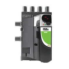
Block drives
Closed-loop vector AC drives for drawing blocks; common DC bus applications.

Motors
Block and spooler motors; high-efficiency induction or permanent magnet motors.
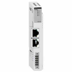
Remote I/O
Remote I/O for dancer positions, wire break detection, die boxes and safety signals.
Field reference
The architecture on this page is built on the drive and control platform ONX Control uses in load sharing, winder tension control and DC to AC retrofit applications. We work out your machine's block count and drive structure together in a meeting.
Retrofit scenario
A typical picture on wire drawing machines: DC motor blocks, speed ratios set by hand with potentiometers, analog dancer circuits, frequent wire breaks and blocks stopping at different times in an emergency. In a retrofit the blocks, die boxes and spooler mechanics are kept; the drives are renewed or moved to AC and the speed cascade and dancer control move to one controller.
- Surveying block motors, dancers and the spooler
- Renewing block drives or moving from DC to AC; designing a common DC bus
- Moving the speed cascade and dancer PIDs to CODESYS
- Putting die sequences and speeds into recipes
- Commissioning in a planned shutdown and comparing wire break frequency and finishing speed
Frequently asked questions
How are block speeds calculated?
Because volume is conserved, speed is inversely proportional to section: next block speed = previous block speed × (previous diameter / next diameter)². The controller uses this ratio as a feed-forward; the dancer corrects the deviation caused by die wear and wire temperature.
What is wrong if a dancer keeps running to its end?
Usually there is a difference between the diameter in the recipe and the real die diameter, or the die is worn. The controller can estimate this from the dancer's average position and show it to the operator; die change timing can also be tracked from it.
What does a common DC bus bring?
Energy generated by decelerating blocks is used by other motors on the same bus; energy and heat dissipated in brake resistors are reduced. With an active front end feeding back to the mains, energy savings rise further.
How is control different on a wet drawing machine?
On a wet (slip) machine the steps turn from one motor and the wire slips on the steps; the speed ratio is fixed mechanically. Control focuses on the main motor, annealer current and spooler tension.
What information is needed for a quote?
Material, inlet and outlet diameters, number of blocks and motor ratings, finishing speed, spooler type and the existing control and drive system are enough for a first assessment.
Discuss the drive and speed control of your wire drawing machine with our engineers
Share your block count, diameters and finishing speed target; we will come back with drive sizing and a control architecture proposal.