
 Control Techniques
 Estun Automation
 CODESYS
 Crevis
 Nexcom / Nexcobot
 Leroy-Somer
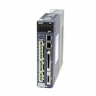 Servo Systems
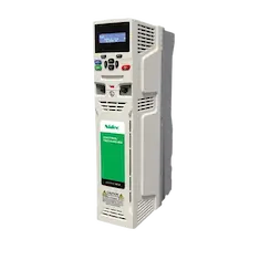 AC Drive + Motor
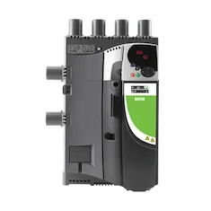 DC Drives
 Smart PLC
 Panel PC / IPC
 Remote I/O
Cable Stranding and Insulation Line Automation
By the ONX Control engineering team · Last updated:
In short
After wire drawing, cable production continues with two main processes: a stranding machine lays wires or cores around each other at a set lay length, and an insulation line coats the conductor with plastic or rubber using an extruder. In stranding, quality is set by the lay length (the length the cable advances in one full turn); it is capstan line speed divided by rotor speed and has to stay constant when speed changes. In insulation, extruder output, capstan speed and diameter measurement set the coating thickness together. ONX Control builds the drive and synchronization control of cable machines with CODESYS, EtherCAT, AC and servo drives.
How it works
There are three main types of stranding machine. On a rigid (cage) strander the bobbins sit on a rotating cage and the wires meet in the closing die as the cage turns; used for conductor and core stranding in power cable. On a tubular strander the bobbins stay still inside a tube and the wires run over the rotating tube; it reaches higher speeds. On a double-twist buncher the reel is stationary and a rotating bow gives two twists per turn; used for bunching fine wires. In all of them rotor, capstan and take-up are the three main axes.
Lay length is capstan line speed divided by rotor speed: lay (mm) = capstan speed (mm/min) / rotor speed (rpm); on a double-twist machine, which gives two twists per turn, this value is halved. On mechanical machines the ratio is fixed by a gearbox and gears are changed at product changes. On an electronic machine the rotor and capstan are driven by separate motors and the ratio is held by an electronic gear in software; lay length changes from the recipe and the ratio is held during acceleration and deceleration. Taping and armouring heads also turn in ratio to line speed in the same way.
The tension of every wire on the pay-off bobbins has to be equal; otherwise one wire is looser than the others in the strand. Tension is held by brakes, dancers or motorized pay-offs. On the take-up, motor speed drops as the reel diameter grows and tension is held by torque calculated from diameter or by a dancer; a traversing guide shifts the cable by one cable diameter per reel turn to build even layers and reverses at the reel flange.
An insulation line runs in this order: pay-off, preheater, extruder and crosshead, cooling trough, diameter and eccentricity gauge, spark tester, capstan, accumulator and take-up. Coating thickness is set by the ratio of extruder output to capstan speed; the diameter gauge signal corrects extruder speed or capstan speed in closed loop. On fast lines an accumulator keeps the line running during reel changes.
-
1
Pay-off
Pay-off bobbins feed wires or cores at equal tension.
-
2
Stranding or coating
The rotor turns geared electronically to the capstan; on an insulation line the extruder coats the conductor.
-
3
Pulling and measuring
The capstan sets line speed; diameter measurement corrects coating thickness in closed loop.
-
4
Take-up
The traversing take-up winds the cable onto the reel in even layers with tension adjusted for diameter.
Critical parameters
| Parameter | Why it matters | Typical range / ONX field data |
|---|---|---|
| Lay length and tolerance | Sets cable flexibility, diameter and compliance with the standard; depends on the accuracy of the rotor to capstan ratio. | Defined per project |
| Rotor speed | Cage or bow inertia and unbalance limit speed; the main factor setting line capacity. | Defined per project |
| Line speed | Capstan speed; directly related to lay length and rotor speed. | Defined per project |
| Pay-off tension | Must be equal between wires; a loose wire causes bulging and diameter deviation in the strand. | Defined per project |
| Coating thickness and diameter | Set on insulation lines by the ratio of extruder output to capstan speed and by diameter measurement. | Defined per project |
| Take-up tension and traverse pitch | Set even reel filling without crushing the cable; traverse pitch should equal cable diameter. | Defined per project |
ONX architecture
In the ONX architecture the capstan is the line master; rotor, taping and armouring heads are geared to it electronically in CODESYS SoftMotion, and lay length changes from the recipe. All axes run on the same ramp so the ratio is held during acceleration, deceleration and emergency stops; braking energy of heavy rotors is managed by regenerative or common DC bus drive structures.
Pay-off and take-up tension are held by dancers or by diameter calculation and torque control; the traverse axis is cammed to take-up speed and flange positions come from the recipe. On insulation lines the extruder, capstan and diameter gauge are on the same controller; thickness is corrected in closed loop and heating zones are held by PID.

CODESYS SoftMotion
Electronic gear to the capstan, lay length recipe, traverse cam and tension control.

Industrial PC
Industrial PC running CODESYS Control RTE, recipes and the line screen.

Rotor and capstan drives
High-power AC drives with encoder feedback for heavy rotors and capstans.
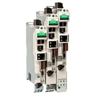
Servo drives
EtherCAT servo drives for the traverse axis and precise positioning.

Motors
Induction or permanent magnet motors for rotor, capstan, extruder and take-up.
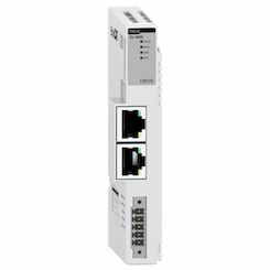
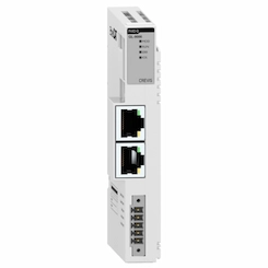
Remote I/O
EtherCAT remote I/O for dancers, wire break detection, spark tester and safety signals.
Field reference
The architecture on this page is built on the electronic gear and traverse cam platform ONX Control uses in winder tension control, load sharing and textile yarn machines. We work out your machine's axis layout together in a meeting.
Retrofit scenario
A typical picture on cable machines: lay length fixed by a gearbox with gears changed at every product change, DC motor capstan and rotor, a mechanical traverse or one with no spare parts and pay-offs with tension set by hand. In a retrofit the rotor, capstan and take-up mechanics are kept; an electronic gear replaces the gearbox, the drives are renewed and lay length changes from the recipe.
- Surveying rotor inertia, capstan, pay-offs and take-up
- Sizing rotor and capstan drives; choosing a drive structure for braking energy
- Holding lay length with an electronic gear in CODESYS and moving it to recipes
- Renewing traverse and take-up tension control
- Commissioning in a planned shutdown and verification with measured lay length
Frequently asked questions
How is lay length calculated?
Lay length is the length the capstan pulls per minute divided by the rotor's turns per minute. For example, with the capstan pulling 30 m/min and the rotor turning at 300 rpm, lay length is 100 mm. A double-twist machine gives two twists per turn, so with the same values lay length is 50 mm.
What does an electronic gear bring instead of a gearbox?
Lay length changes from the recipe with no stop for gear changes, and the ratio is held during acceleration and deceleration. Taping and armouring heads are also geared to line speed by the same software.
How is braking of a heavy rotor handled?
Large cage rotors have high inertia; the energy released when slowing down can be burned in a brake resistor, fed back to the mains or used by other axes on a common DC bus. In an emergency stop it matters that all axes stop while holding their ratio, so the cable does not break.
How is coating thickness held constant on an insulation line?
The ratio between extruder output and capstan speed sets thickness. The diameter gauge signal corrects extruder speed or capstan speed in closed loop; during speed changes the extruder follows the capstan in ratio.
What information is needed for a quote?
Machine type, number of bobbins, rotor speed, line speed and lay length range, cable diameter range, take-up reel sizes and the existing control and drive system are enough for a first assessment.
Discuss the stranding and line sync of your cable machine with our engineers
Share your machine type, rotor speed and lay length range; we will come back with drive sizing and an architecture proposal.