Flying Splice Automation
In short
A flying splice is an automatic roll change on printing, packaging and converting lines in which the web of an expiring roll is pasted to a new roll and cut, without stopping the line or reducing speed. The new roll is first spun up until its surface speed equals the web speed; when the prepared adhesive tape reaches the right position, the web is pressed onto the new roll, the old web is cut and tension control is handed over to the new roll. ONX Control builds this sequence with CODESYS, EtherCAT and servo and AC drives.
How it works
On a dual-arm or turret unwinder, one roll feeds the line while the new roll in the second position is prepared with double-sided adhesive tape and a tab. When the expiring roll's diameter falls to a set threshold, the splice sequence starts. The new roll's diameter is measured or entered, and motor speed is set with n = v / (π × D) so that the roll's surface speed equals line speed. If the speed match is off, the web is stretched, breaks or goes slack at the moment of splicing.
Once speed is matched, the roll's angular position is tracked from the encoder or from a mark on the tape. When the adhesive tape reaches the contact point, a brush or pasting roller presses the web onto the new roll, and after the tape has passed, a knife cuts the old web. The new roll is then switched from speed control to tension control and the expiring roll is braked to a stop. In a zero-speed splice, by contrast, the roll is stopped and the splice is made at standstill, while the line is fed from material stored in an accumulator (festoon).
-
1
Preparation and diameter threshold
Adhesive tape is applied to the new roll; the expiring roll's diameter is calculated continuously and the splice sequence starts at a set threshold.
-
2
Surface speed match
The new roll is accelerated according to its measured diameter until its surface speed equals line speed; if line speed changes, the reference follows.
-
3
Pasting and cutting
The roll's angular position is tracked; when the tape reaches the contact point the web is pressed onto the new roll and the old web is cut right after.
-
4
Tension handoff
Tension control passes to the new roll and the expiring roll is braked; where needed, the splice section is marked for rejection downstream.
Critical parameters
| Parameter | Why it matters | Typical range / ONX field data |
|---|---|---|
| Line / web speed | Sets the speed the new roll must reach, its acceleration time and how early the sequence must start. | Defined per project |
| Speed match and splice position accuracy | Surface speed difference and the timing of the tape reaching the contact point decide whether the splice holds; diameter measurement accuracy is critical. | Defined per project |
| Sequence time and response time | The sum of acceleration, matching, pasting and cutting; brush and knife trigger delays directly shift the splice position. | Defined per project |
| Roll diameter and weight | Determine motor torque, acceleration time and braking energy, and are needed to calculate how often rolls change. | Defined per project |
| Material and adhesive | Paper, film, foil or laminate; thickness, elasticity and adhesive type set pasting pressure and tension tolerance. | Defined per project |
ONX architecture
In the ONX architecture the unwind spindles, turret rotation, pasting brush and knife axes share one EtherCAT network. Diameter calculation, surface speed matching, tracking the roll's angular position and calculating the moment of pasting and cutting run in CODESYS; timing-critical outputs are triggered by position.
Tension control after the splice uses the same structure as winder and unwinder tension control, with diameter calculation and dancer or load cell loops. On zero-speed splice lines with an accumulator, accumulator level, unwinder speed and line speed are managed together, and the accumulator is refilled after the splice.

CODESYS SoftMotion
Surface speed matching, roll angular position tracking, position-based pasting and cutting triggers, tension handoff.

Industrial PC
Industrial PC or panel PC running CODESYS Control RTE.

Unwind spindle drives
EtherCAT drives running in speed and torque control.
Servo axes
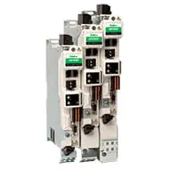
Servo drives and motors for fast, position-controlled axes such as turret rotation, pasting brush and knife.
Remote I/O
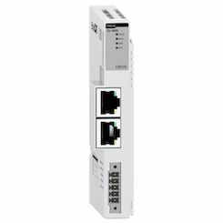
EtherCAT remote I/O for splice tape sensor, diameter sensor, dancer, load cell and pneumatic valves.
Field reference
The image below illustrates the principle of a flying splice: the web is pasted between the expiring roll and a new roll brought up to line speed, and the old web is cut.
Principle illustrations

Retrofit scenario
A typical picture on existing unwinders: the line is slowed down or stopped for every roll change, splice timing is done with fixed delays in an old PLC, and the drives have no spare parts. In a retrofit the unwinder mechanics, turret and pneumatics are usually kept; drives, controller and sensors are renewed and the splice sequence is moved to a position-based structure that adapts itself to line speed.
- Inspecting the existing unwinder, turret, brush and knife mechanism and sensors
- Selecting torque-controlled drives for unwind spindles and servo drives for fast axes
- Moving diameter calculation, surface speed matching and the splice sequence to CODESYS
- Adding encoders and sensors for roll angular position and splice tape detection
- Commissioning with trial splices at different speeds and roll diameters
Frequently asked questions
What is the difference between a flying splice and a zero-speed splice?
In a flying splice the new roll is brought up to line speed and the splice is made while the web is moving; no accumulator is needed, but speed matching and timing must be precise. In a zero-speed splice the unwinder stops and the splice is made at standstill; meanwhile the line is fed from material stored in an accumulator.
How is the new roll matched to line speed?
The new roll's diameter is measured or entered, and motor speed is calculated so that the roll's surface speed equals line speed. If line speed changes before the splice, the reference is updated continuously.
How is the moment of splicing determined?
The new roll's angular position is tracked from the encoder or from a mark on the adhesive tape. Brush and knife are triggered from the moment the tape reaches the contact point, taking the system's trigger delays into account.
How is tension held during the splice?
Until the splice, tension is carried by the expiring roll. After the splice, tension control passes to the new roll and the expiring roll is braked. The dancer or load cell loop absorbs the short disturbance during this transition.
What information is needed for a quote?
Line type, material, line speed range, roll diameter and weight, unwinder type (dual-arm, turret), preference for flying or zero-speed splicing and the existing control system are enough for a first assessment.
Discuss your flying splice project with our engineers
Share your material, line speed and roll dimensions; we will come back with a splicing method and control architecture proposal.