
 Control Techniques
 Estun Automation
 CODESYS
 Crevis
 Nexcom / Nexcobot
 Leroy-Somer
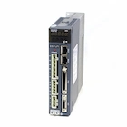 Servo Systems
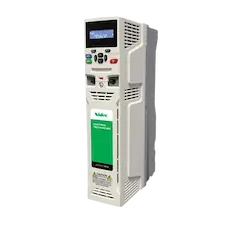 AC Drive + Motor
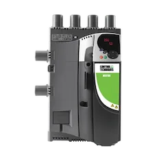 DC Drives
 Smart PLC
 Panel PC / IPC
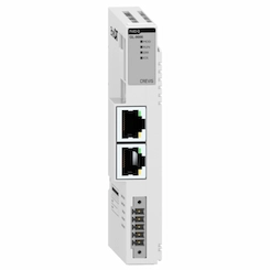 Remote I/O
Videos
ONX Control field and test videos: flying shears and rotary knives cutting moving material, winders, CNC machines, packaging lines and CODESYS applications.
 4:29
5-Axis CNC Test: Flower Medallion (X CNC Library)
X CNC Library runs a demanding 5-axis (X Y Z A C) test program on CODESYS Control RTE; the footage is from the web HMI path view, in real time. The program has 640 mm long lines, R40 arcs and 45° chamfers, arches in the XZ and YZ planes, a wave fringe where the tool tilt (A) follows the slope, a diamond zigzag down to 0.6 mm pitch and a wavy ring of 0.1 mm micro segments.
 1:09
Onx CNC RTCP: 5-Axis Tool Center Point Control (X CNC Library)
RTCP (tool center point control) with X CNC Library and the Onx CNC web HMI, live on CODESYS Control RTE. M140 in the program switches RTCP on; X Y Z then describe the tool tip instead of the head, and F is the tip speed. While the A/C head rotates, the controller corrects X Y Z and keeps the tool tip on the programmed path. In the video: the tip stays still during an orientation-only move (A 30°, C 360°), a straight line while the tool tilts and an arc (G2) with a tilted tool, a G0 with changing orientation and a 3+2 (A −45°) plunge, a straight line while C turns 180°, and the return to machine coordinates with M141. 1 ms interpolation, look-ahead and jerk-limited planning; virtual axes, A/C fork head, pivot to tip 150 mm.
 2:05
Onx CNC Web HMI: 5-Axis Turbine, 139,882 Lines of G-code
A live run of a 139,882-line 5-axis (X Y Z A C) turbine rosette program on CODESYS Control RTE with X CNC Library and the Onx CNC web HMI. In the video: starting the job with one click and the live job status, the real-time 3D path view (program, executed part, command and actual path), the tool axis from A/C, override while running with path velocity, acceleration and jerk charts, colouring the path by C axis or F, 1 ms live trace, the built-in G-code editor and the axis min/max limits over the job. 1 ms interpolation, look-ahead planning, virtual axes.
 0:36
17-Axis Servo Cake Packaging Line: Smart Belt and Lug Chain
A 17-axis servo cake packaging line automated by ONX Control, in 36 seconds. Randomly spaced cakes are buffered on an accumulation belt; the smart belt detects every product with a photo-eye, gaps it and puts it in phase with the packaging machine's master axis. A lug chain transfers the cakes to the horizontal flow wrapper in sync; print registration is corrected on every pack and the rotary jaws seal and cut. The operator panel shows a machine speed of more than 600 packs per minute.
 0:33
Automatic Pocket Setter: X-Y Servo Sewing and Mould Folding
A bathrobe pocket on an automatic pocket setter: the operator places the pocket on the mould, the mould folds it and carries it to the panel, the sewing head follows the stitch path with X-Y servo axes in sync with the needle, and the finished part is stacked automatically. Control runs on CODESYS on an industrial PC, with Estun ED3L EtherCAT servo drives on the X-Y axes and Crevis I/O for folding and stacking.
 3:27
Kangaroo Pocket Setter: CODESYS CNC Control and Thickness Algorithm
Custom kangaroo pocket machine automation: CNC-controlled motion, a thickness control algorithm and synchronised motion for repeatable production. Control is based on CODESYS.
 0:34
CNC Router Control System: Furniture Panels, Composites and MDF
Field footage from CNC routers controlled by ONX Control: MDF and furniture panel cutting, composite contours and hinge holes. G-code and look-ahead velocity planning run on X CNC Library, control on CODESYS Control RTE on an industrial PC, and the axes on EtherCAT servo drives.
 0:36
Tissue Converting Line: Non-Stop Rewinder, Log Saw and Core Maker (Kenya)
Field footage from Kenya of a tissue (toilet and kitchen towel) converting line controlled by ONX Control: parent roll unwinder, servo perforation, change to a new core on the non-stop rewinder, core maker and log accumulator. Control runs on CODESYS; the tear moment is calculated from sheet count and perforation angle, so the paper tears at the perforation line every time.
 2:56
17-Axis Cake Packaging Line
Field footage of ONX Control's 17-axis cake packaging line. Products are fed to the horizontal packaging machine in phase by a smart belt and a lug chain.
 1:25
Double-Head Flying Saw
Field footage of a double-head flying saw application: the saw carriage cuts in sync with the speed of a tube and profile line without stopping it.
 0:52
Double-Head Flying Shear Control (CODESYS SoftMotion CNC)
Control of a double-head flying shear with CODESYS SoftMotion CNC: the cutting carriage synchronizes to line speed with an electronic cam.
 0:40
Rotary Knife Automation: Servo Synchronization
An ONX Control application where a rotary knife cuts running material in servo synchronization.
 0:39
Rotary Shear Control: CODESYS RTE and EtherCAT
An ONX Control application where rotary shear control is synchronized with CODESYS Control RTE and EtherCAT.
 0:30
Rotary Knife 15 mm: Dual-Motor CODESYS RTE and EtherCAT Application
A dual-motor rotary knife application, controlled with CODESYS Control RTE and EtherCAT.
 1:30
Tension-Controlled Winder Application
Field footage of a tension-controlled winder application.
 0:14
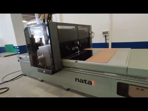
CNC Router: CODESYS SoftMotion CNC Based Control
Control of a CNC router based on CODESYS SoftMotion CNC.
 2:40
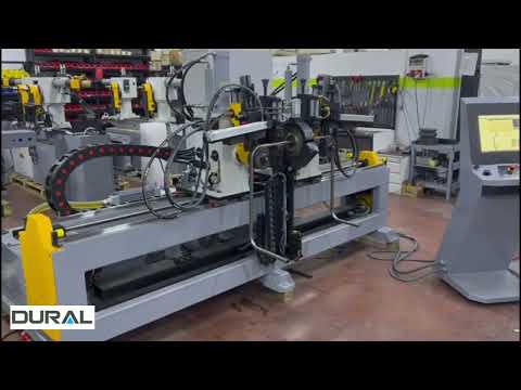
3-Axis CNC Router: CODESYS SoftMotion CNC Application
Control of a 3-axis CNC router with CODESYS SoftMotion CNC.
 0:49
Fully Automatic Tube Bending Machine: CODESYS Based Control
Field footage of a fully automatic tube bending machine running on a CODESYS based control system.
 0:37
Four-Corner Welding, Robot and Cleaning Line
Field footage of a four-corner welding, robot and cleaning line application.
 1:04
Thermoform Packaging Machine
Field footage of a thermoform packaging machine application.
 1:22
High-Speed Bottle Filling Machine Automation
Field footage of the automation of a high-speed bottle filling machine.
 1:57
PLC Programming Basics with CODESYS
The first part of a training series on the basics of PLC programming with CODESYS.
 1:55
ONX Control Company Introduction: PC-Based Automation, Servo and Motion Control
ONX Control's PC-based automation, servo and motion control for machine builders since 2013, in two minutes. Every machine in the video is a real field application: flying shear, rotary knife and tube bending lines, packaging and food, cable extrusion and textile, tissue converting, CNC routers and window machines. Our own software X CNC Library, CODESYS and EtherCAT; official partnerships (CODESYS, Nidec Drives, ESTUN, CREVIS, NEXCOM) and projects in 18 countries.
 1:09
Servo Motor Sizing Calculator: Torque, Inertia Ratio and Motor Selection
Sizing the motor for a ball screw axis with ONX Motion Sizing, in one minute. In the video: choosing the mechanism, the load (50 kg carriage, Ø25 mm ball screw with 20 mm lead), the motion profile (300 mm in 0.6 s, 1/3 trapezoid, 0.4 s dwell), the reduction chain, safety margins and the inertia ratio limit; then peak and RMS torque, motor speed, inertia ratio and matching servo motors, switching between metric and imperial units, and the formulas, worked example and FAQ on the page. The tool is free and needs no sign-up.
 6:43
Servo Motor vs Stepper Motor: How to Choose
Servo motor vs stepper motor explained: open-loop steps vs closed-loop encoder feedback, torque-speed curves and how to choose, with a sizing example. A stepper motor counts pulses and runs open loop; if the load or the acceleration asks for too much, it misses steps and the controller never knows. A servo motor measures its position with an encoder (a 23-bit encoder resolves 8,388,608 positions per revolution) and corrects errors with the position, velocity and current loops in its drive. The video covers torque-speed curves, a side-by-side comparison, when to choose which, field footage of an ONX flying shear and 17-axis cake line, and the ball screw example from our motor sizing guide: 2,250 rpm and 8.08 kg·cm² load inertia; an inertia ratio of 33 with a 0.4 kW low-inertia motor and 4.9 with a 0.75 kW medium-inertia motor.
 5:52
VFD Explained: How a Variable Frequency Drive Works
How a variable frequency drive works: rectifier, DC bus and IGBT inverter, PWM, control modes, energy savings, braking and harmonics, in 5:52. An induction motor's speed follows the supply frequency (n = 120·f/p; a 4-pole motor turns at 1,500 rpm on 50 Hz). Inside a VFD are a rectifier, the DC bus (around 560 V DC on a 400 V supply) and an IGBT inverter that builds a new three-phase output with PWM. The video covers V/f, sensorless vector and closed-loop vector control, the cube law on pumps and fans (about 51 % power at 80 % speed), braking and regeneration (ramp, braking resistor, active front end), harmonics and practical installation tips.
 5:13
PID Controller Explained: Tuning and Winder Tension
PID control explained: what P, I and D do, how to tune a loop, and feed-forward plus PID for winder tension control, in 5:13. On one simulated step response, P alone leaves an offset and overshoots as the gain rises; I removes the offset but adds overshoot and needs anti-windup; D damps the overshoot but amplifies noise, so it is filtered. Tuning: a step test (gain, dead time, time constant), P first, then I, D only if needed, output limits and trend logging. On a winder, motor torque is T = F·r/(i·η): feed-forward from the calculated diameter does most of the work and the PID trims the rest with a dancer or a load cell; taper tension and field footage of an ONX tension-controlled winder.
 6:07
Cable Sizing Explained: Voltage Drop, Ampacity and Short Circuit
The five IEC 60364 checks for sizing a cable, with a worked example of a 22 kW motor 80 m from the panel, in 6:07: current-carrying capacity (the same 16 mm² copper PVC cable carries 52–62 A in conduit, 76 A clipped direct and 80 A on a perforated tray; 57 A with 0.87 at 40 °C and 0.82 for three circuits), overload protection (I_B ≤ I_n ≤ I_z), voltage drop (3 % lighting, 5 % other loads; also during motor starting), short-circuit withstand (k²S² ≥ I²t; at least 14.8 mm² copper XLPE for 15 kA cleared in 20 ms) and the earth fault loop (with a type C 50 A breaker the maximum length is 48 m on 6 mm² and 81 m on 10 mm²). Harmonics in the neutral, and the result: current alone says 6 mm², but the breaker and the fault loop need 10 mm².
 8:01
DC to AC Motor Conversion: Retrofit, Vector Control and Payback
Convert a DC motor drive to AC, or keep the DC motor and renew the drive? In 8:01: on a DC motor, torque follows the armature current (T = k·Φ·I_a) and speed follows the armature voltage, with field weakening above base speed. The costs of DC: brush and commutator wear, a power factor that falls with speed on thyristor drives, ageing drives and commutator sparks. A closed-loop vector drive splits the stator current into I_d, which sets the flux, and I_q, which produces torque: full torque at zero speed, constant torque up to base speed and constant power above it, up to the AC motor's breakdown torque limit. Before you convert: torque at base speed and power at top speed, a separately driven fan for low-speed duty, mechanical fit, an encoder instead of an analog tacho; a four-quadrant DC drive regenerates to the grid, a standard AC drive with a diode rectifier cannot (braking resistor or active front end); shielded cable and insulated bearings. Worked example (the calculator's default inputs): 90 kW shaft power, 84 % vs 94 % efficiency, 6,600 hours a year → €10,532 energy, €35,532 total annual gain, 13.2 months payback on a €39,000 net investment.
 7:22
Encoder Explained: Incremental vs Absolute, Resolution and Signals
How an encoder works and how to choose one, in 7:22. Optical and magnetic encoders; on an incremental encoder, channels A and B are 90 degrees apart and give the direction, Z gives one index pulse per revolution, and counting every edge turns 2,500 lines into 10,000 counts per revolution. An incremental axis loses its position at power-off and must home; a Gray-code absolute encoder knows its position at power-up, and a multi-turn one counts revolutions with gears or a battery-backed counter. Resolution: 17 bit = 131,072, 20 bit = 1,048,576, 23 bit = 8,388,608 counts per revolution (364 / 2,913 / 23,302 per degree); at 1 rpm a 17-bit encoder moves about 2 counts per millisecond and a 23-bit one about 140, so low-speed motion is much smoother. Resolution is not accuracy. Signals: TTL/RS-422, HTL, SinCos, SSI, EnDat, Hiperface, BiSS and resolver. Motor encoder vs measuring wheel, field footage of an ONX rotary shear for 15 mm plate (the knife follows the line encoder, 10–80 m/min, ±0.5 mm), and five checks for choosing.
 8:15
What is CNC? How CNC Machines Work
What CNC (computer numerical control) is and how a CNC machine turns a drawing into a part, in 8:15. From punched-tape NC to computer CNC; the control chain: CAD → CAM → G-code → CNC controller → interpolator → servo drive → motor → axis. Interpolation turns the path into a position target for every axis in every cycle (at 6 m/min the tool moves 0.1 mm per 1 ms); the servo drive compares the target with the encoder position and corrects the following error with position, speed and current loops. 3-, 4- and 5-axis machines and RTCP; milling machines, lathes, routers, plasma, laser, waterjet, punch presses and wire EDM; the parts of a machine tool; resolution vs repeatability vs accuracy; real time and jitter in PC-based CNC. A 139,882-line 5-axis turbine program from an ONX X CNC Library lab test (virtual axes) and the free DXF to G-code converter.
 8:27
What is G-code? CNC Programming Explained, Line by Line
What G-code is and how a CNC controller reads it, in 8:27. Plain text based on RS-274 / ISO 6983: every line is a block, every word a letter and a number (N, G, M, X/Y/Z, I/J/K, F, S, T). Modal commands; G0 rapid positioning and G1 linear feed; G2/G3 arcs with I/J or R and the G17/G18/G19 planes; G20/G21 units, G90 absolute and G91 incremental positioning; G54–G59 work offsets and G53; G43 H tool length and G41/G42/G40 D cutter radius compensation; M3/M4/M5, M6, M8/M9, M0/M1 and M30. A complete program for an 80 × 50 mm plate with an R10 corner, line by line; how CAM and the post processor write G-code for a dialect; the interpreter, look-ahead and interpolator inside the controller. The codes shown are generic ISO/Fanuc style; every controller has its own dialect (X CNC takes feed in mm/s).