
 Control Techniques
 Estun Automation
 CODESYS
 Crevis
 Nexcom / Nexcobot
 Leroy-Somer
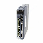 Servo Systems
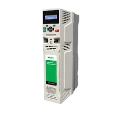 AC Drive + Motor
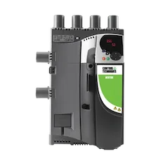 DC Drives
 Smart PLC
 Panel PC / IPC
 Remote I/O
X CNC Library · free online tool
DXF to G-code converter
Upload your DXF drawing: all geometry including lines, arcs, polylines, ellipses, blocks and splines is converted to G-code for X CNC and CODESYS SoftMotion CNC. Click a piece in the drawing to see its G-code line, or click a line in the list to see it in the drawing.
- Processed in your browser, never uploaded
- Splines → adjustable G1 pieces
- Line ↔ drawing link
- Toolpath simulation
How to use it
-
1
Open the DXF
Drop or choose the file. The unit is read from the file; you can switch layers and entity types on and off.
-
2
Pick the settings
Spline piece length, arc format, feed, depth and step-down. The G-code is regenerated on every change.
-
3
Check it
Click a piece or a line to see its source and length. Watch the cutting order in the simulation.
-
4
Download
Load the .cnc file on the X CNC controller or in the web HMI.
Supported DXF entities
| DXF | Coverage | G-code |
|---|---|---|
| LINE | Line | G1 |
| ARC · CIRCLE | Arc and circle (a full circle is one line) | G2 / G3 |
| LWPOLYLINE · POLYLINE | Polylines with bulges (arc segments), 2D and 3D | G1 + G2 / G3 |
| SPLINE | NURBS: rational, periodic, closed, fit points only | equal-length G1 |
| ELLIPSE | Full ellipse and elliptical arc | equal-length G1 |
| INSERT | Blocks, arrays (MINSERT), rotation, mirror, nested blocks | transformed geometry |
| HATCH | Hatch boundaries (optional) | G1 + G2 / G3 |
| SOLID · TRACE | Outline of the filled area | G1 |
| POINT | Drill or mark point | G1 Z / G4 |
| TEXT · DIMENSION · 3D | Text, dimensions, 3D solids: skipped and listed | – |
X CNC and CODESYS compatibility
- One G code per line: G90, G17 and G51 on separate lines (the CODESYS interpreter rejects two G codes in one line).
- No spline codes (G5, G6, G10): curves become equal-length G1 moves that X CNC merges with G38 O1 and smooths; corners are rounded with G51 D.
- Arcs as G2/G3 with I/J relative to the start point; a full circle is a single line.
- Feed F in mm/s, written only when it changes.
- No cutter compensation (G41/G42/G43): the path is the tool centre.
- Comments in parentheses, ASCII only; the program ends with M30.
Frequently asked questions
Is my DXF file uploaded to a server?
No. The file is read and the G-code is generated in your browser; the drawing is not sent to the ONX Control server. Nothing is kept once you close the page.
How should I choose the spline piece length?
Splines and ellipses are split into G1 pieces of equal length. A piece deviates from the curve by about L² / (8·R) at most (L piece length, R radius of curvature): for L = 0.5 mm and R = 10 mm that is ≈ 0.003 mm. Shorter pieces are more accurate but give more lines; X CNC merges short G1 moves with G38 O1 and smooths them into fluid motion.
Why do separate lines become one contour?
Lines, arcs and splines whose ends meet within the join tolerance are chained into one contour, so the tool does not lift between pieces. If the ends do not meet, the contour stays open and a warning is shown.
Is tool radius compensation applied?
No. X CNC does not support G41/G42 cutter compensation; the drawing is converted as the path of the tool centre. If the part size matters, offset the drawing by the tool radius in your CAD program.
Why is the feed (F) in mm/s?
X CNC and the CODESYS SoftMotion CNC interpreter read the feed in units per second: F is the cutting and plunge feed, FF the G0 speed (both mm/s). For example F20 = 20 mm/s = 1200 mm/min.
Which DXF versions can be read?
ASCII DXF (R12 and later) is read. Binary DXF is not supported; save the file as ASCII DXF in your CAD program. Text, dimensions and 3D solids are not converted and are listed separately.
Planning a CNC project?
Toolpaths up to 5 axes on your CODESYS machine with X CNC Library
In this section