
 Control Techniques
 Estun Automation
 CODESYS
 Crevis
 Nexcom / Nexcobot
 Leroy-Somer
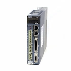 Servo Systems
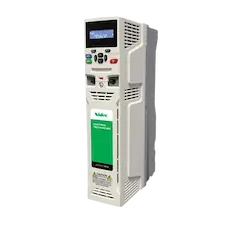 AC Drive + Motor
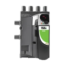 DC Drives
 Smart PLC
 Panel PC / IPC
 Remote I/O
VFD Investment Return Analysis
When you switch from mechanical throttling (damper/valve) to an AC Drive in your fan and centrifugal pump applications; instantly see the drop in your electricity bill, the reduction in your carbon footprint, and how many months the investment will pay for itself.
Laws of Physics
Changes directly proportional to speed.
Changes proportional to the square of speed.
Reducing speed by 20% reduces energy consumption by approximately 50%!
1 System and Application Data
Average mechanical efficiency of Motor + Drive.
2 Operational and Financial Profile
Throttling (Damper) vs. VFD Power Curve
Financial Analysis Result
Engineering Expert Window
System Dynamics and Retrofit Risks
Static Head (Dead-Head)
Drive speed should not be reduced randomly without analyzing the System Curve. Especially in pumps, a minimum operating frequency (e.g., 30 Hz) is required to overcome gravity or constant system pressure (Static Head). Falling below this speed causes the pump to spin without pumping fluid (Dead-Head); this leads to mechanical seal burns and cavitation.
Bearing Currents and Insulation Class
When modernizing (Retrofitting) older generation (grid-fed) asynchronous motors with a VFD, the high dV/dt (rate of voltage rise) caused by the drive's PWM waves can puncture winding insulation or cause Bearing Currents leading to mechanical failure. If necessary, a Motor Choke should be used.
Frequently Asked Questions
Why does energy consumption drop by the "cube" of speed?
Due to the physics of centrifugal loads, flow rate changes linearly with speed, and pressure is proportional to the square of the speed. Since work done is (Power = Flow × Pressure), Power changes with the cube (3rd power) of speed. Therefore, a fan running at 80% speed draws only about (~51%) of the power it would at full speed.
Is this calculation valid for constant torque loads (Conveyor, Crane, Extruder)?
Is there an efficiency difference between "Bypass" and "Valve/Damper Throttling"?
Yes. In Bypass (Recirculation) systems, fluid is returned from the line, and the motor continues to run continuously at 100% full power; it is the most inefficient method. With Valve/Damper throttling, a physical resistance (blockage) is created in the line, the power drawn by the motor drops slightly, but the fluid hits the valve, wasting energy as heat and noise. A VFD (AC Drive) provides the highest efficiency by reducing energy directly at the source.
How does using a drive affect the compensation system or harmonics?
Modern VFDs meet the motor's reactive power demand via their own DC bus, which raises the Power Factor (Cosφ) drawn from the grid to around 0.98, incredibly lightening the load on the compensation panel. However, drives emit THDi (Current Harmonics) into the grid. Therefore, for high power ratings, ONX drive solutions with Chokes (DC/AC) or Low Harmonic / AFE structures should be preferred over standard drives.

How a variable frequency drive works
How a drive sets the speed and why the cube law brings large savings on pumps and fans, in a 5:52 video.
- Rectifier, DC bus and IGBT inverter
- About 51 % power at 80 % speed
- Braking, harmonics and installation tips
How to calculate VFD energy savings on pumps and fans
In many plants fans and pumps run at full speed while the flow is throttled with a damper, valve or bypass, and the motor keeps drawing most of its power. A variable frequency drive (VFD) sets the flow by lowering the speed; since power on centrifugal machines falls with the cube of speed, savings at part load are large. This tool compares the old method with a drive at the same flow and calculates the payback.
| Speed | Flow Q ∝ n | Pressure H ∝ n² | Power P ∝ n³ |
|---|---|---|---|
| 100 % | 100 % | 100 % | 100 % |
| 90 % | 90 % | 81 % | 72.9 % |
| 80 % | 80 % | 64 % | 51.2 % |
| 70 % | 70 % | 49 % | 34.3 % |
| 60 % | 60 % | 36 % | 21.6 % |
| 50 % | 50 % | 25 % | 12.5 % |
- Pold = Prated · f(Q) / ηold
- PVFD = Prated · Q³ / ηVFD
- Saving [kWh] = (Pold − PVFD) · hours
- Payback [months] = investment / annual saving · 12
f(Q) is the old method's power ratio at a given flow; the tool approximates it as 0.45 + 0.55·Q for a damper, 0.30 + 0.70·Q for an inlet guide vane and 0.70 + 0.30·Q for a bypass. Default efficiencies: 0.90 for the old system, 0.96 with the drive. If you have a measured power, the measured mode replaces these estimates.
Worked examples
Energy price 0.14 €/kWh; investment amounts are examples, enter your own quote.
| 75 kW fan, damper | 15 kW fan, inlet guide vane | |
|---|---|---|
| Flow, operation | 80 % · 20 h × 330 days | 70 % · 16 h × 300 days |
| Power, old method | 74.17 kW | 13.17 kW |
| Power with drive | 40.00 kW | 5.36 kW |
| Annual energy saving | 225,500 kWh | 37,475 kWh |
| Annual saving | €31,570 | €5,247 |
| Investment (example) | €10,000 | €3,000 |
| Payback | 3.8 months | 6.9 months |
Frequently asked questions
How much energy does a VFD save on a fan or pump?
Savings depend on how far and how often the flow is reduced. On centrifugal fans and pumps the power drawn varies with the cube of speed: at 80 % speed the power is about 51 % of rated. Throttling to the same flow with a damper or valve keeps most of the power. In the tool's example, a 75 kW fan run at 80 % flow on a drive instead of a damper uses about 225,000 kWh less per year.
What are the affinity laws?
On centrifugal pumps and fans, when speed n changes, flow varies as Q ∝ n, pressure or head as H ∝ n², and power as P ∝ n³. That is why a small drop in speed gives a large drop in power: 73 % power at 90 % speed and 34 % at 70 % speed.
Why are pump savings sometimes lower?
The cube law fully applies only to systems dominated by friction. If the pump lifts water to a fixed height (static head), the usable speed range narrows and savings fall below what the cube law suggests. For such systems use the tool's measured-power mode or verify with the pump curve.
What is the difference between damper, inlet guide vane and bypass control?
All three reduce flow while the motor keeps running at full speed. An outlet damper throttles the flow but cuts power only a little; an inlet guide vane is more efficient; a bypass recirculates part of the flow and cuts power hardly at all. The tool uses an approximate power-versus-flow curve for each and compares it with a drive.
What should I measure for a more accurate result?
Measure the power drawn by the existing system (kW) with an energy analyser and record the daily operating profile: how long the flow stays at which level. In the tool's measured mode you can enter that power directly. For the investment, include the drive, filters, panel and commissioning together.
What should I watch when fitting a drive?
At low speed a self-ventilated motor cools less; check the minimum speed and that the motor is suitable for drive operation. A line reactor or filter may be needed for harmonics, and an output filter on long motor cables. On pumps, set minimum flow and dry-run protection in the drive parameters.